
TL;DR: USB3-PIPE ran at 10Gbps on a Kintex UltraScale+ and at 5Gbps on Gowin. Combining the two, 10Gbps on a GW5A, meant running a 128b/132b PHY at 125 MHz on 80-bit words and a link layer at 62.5 MHz on 128-bit words. The transceiver also had to change rate fast enough for the host. It meant handling, correctly, the bit errors that a 10Gbps link through an SFP adapter really has. The Tang Mega 138K Pro now enumerates as a SuperSpeedPlus device and runs Bulk OUT at 750 MB/s, Bulk IN at 620 MB/s and full duplex at 522 + 589 MB/s, with zero data errors and zero Recovery. Most of the fixes are in the shared core and apply to the Xilinx and Lattice targets too.
Why 10Gbps on Gowin#
At 5Gbps the Gowin port already worked, and it now runs in a product: the SLogic16U3 streams 400 MB/s of samples through its GW5AT-15 transceiver. The GTR12 transceivers of the GW5A family go up to 12.5Gbps, so 10Gbps was the obvious next step.
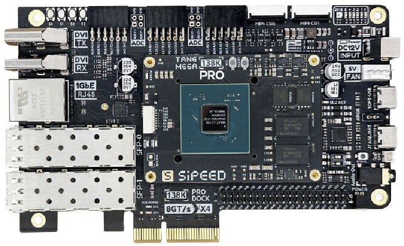
It is also where low-cost instruments are going. Sipeed’s next analyzer, the SLogic32U3, is a USB 3.2 Gen 2 device with 32 channels and about 800 MB/s of streaming. We want USB3-PIPE to be ready for that class of hardware, and the Tang Mega 138K Pro, with its 138K LUTs and SFP cages, is the comfortable place to develop it before a smaller part.
The starting point#
Two pieces existed:
- Gen 2 on the XCKU3P. On the UltraScale+ GTY, the 128b/132b PHY (block aligner, scrambler, gearbox, DC balance) runs at 250 MHz on 40-bit raw words. The link layer runs at 125 MHz on 64-bit words.
- Gen 1 on the Tang. On the GW5AST-138, the PIPE runs in its own 125 MHz clock domain on the GTR12 TX clock. The LTSSM, link layer and core run at 62.5 MHz on 64-bit words.
The Gowin fabric cannot run the Gen 2 PHY at 250 MHz, so on the Tang it stays at 125 MHz, on 80-bit raw words: twice the width of the XCKU3P datapath at half the clock. The link layer stays at 62.5 MHz, and that is where the first problem shows. A 10Gbps link carries about 1.2 GB/s of payload, but 64-bit words at 62.5 MHz move only 500 MB/s.
The transceiver at 10Gbps#
The 10Gbps lane uses the GTR12 channel PLL (CPLL) from the 125 MHz reference, with a 20-bit PMA and a 1:4 gear to the fabric: 80-bit words at 125 MHz at 10Gbps, and 40-bit words at 5Gbps. The starting configuration came from the LiteEth GW5 10GBASE-R lane, which had already validated 10G CPLL clocking, adapted to the USB rates and widths with Gowin’s SerDes tools. A few values had to be found on hardware:
- the CDR VCO bias from the generated configuration does not lock, as on LiteEth, so it is overridden;
- the word aligner is turned off at 10Gbps, where the block aligner in the fabric does that job;
- the RX equalizer is automatic at 5Gbps and manual at 10Gbps. The automatic one does not receive the host through the SFP2USB adapter at 10Gbps, and the manual settings prevent the 5Gbps link, so the settings change with the rate;
- the 10G configuration on the quad PLL (QPLL1, 100 MHz reference) gave bit errors, so the lane uses its own CPLL.
The rate change has to be short. A USB 3 link always starts at 5Gbps. The speed is negotiated with LFPS messages, and only then does the PHY switch to 10Gbps. Right after the switch, the host trains its receiver equalizer on the device’s TSEQ sequence, which lasts about 7 ms at 10Gbps. Our first rate change took about 4 ms: the host never received our TS1 and never sent its TS2. The sequencer now writes five lane registers with the CPLL in reset: the CPLL divider, the CDR, the aligner and the TX/RX gears. It releases the CPLL after 50 µs, waits 200 µs for the lock, and applies the equalizer settings for the new rate. The TX electrical idle control is also written again after each rate change. The writes go through LiteICLink’s runtime register access to the GTR12.
Width instead of frequency#
With the PHY at 125 MHz, the first 10Gbps builds placed the Gen 2 framing in the 62.5 MHz domain with 32 bytes per cycle, and the link layer on 64-bit words. The Tang enumerated as “SuperSpeed Plus Gen 2x1” on the first builds that met timing. Bulk IN ran at 380 MB/s with checked data. Bulk OUT reached 340 MB/s, but it was not reliable: Recoveries, sometimes a re-enumeration.
The bandwidth fix was to widen the link layer again: 128-bit words (link_words=4), 16 bytes
per cycle at 62.5 MHz, about 1 GB/s. That is the same bandwidth as the 64-bit link layer at 125 MHz
on the XCKU3P. It touched more than the link layer:
- a CRC-32 on 128-bit words, with the last 1 to 3 bytes of a packet handled in a registered second stage;
- link layer RX words consumed from a window of words, so that a 16-byte word is accepted once its data is present, and skipped packets advance up to four words per cycle;
- 128-bit Bulk endpoints, packet slots and bench core;
- TX at 16 bytes per cycle, with a Gen 2 framer and packer on 16-byte entries. At first TX stayed at 8 bytes per cycle, which limited Bulk IN to 381 MB/s and delayed the link commands behind the IN data in full duplex.
The 128-bit link layer is also a step toward Gen 2x2, where two 10Gbps lanes need twice the bandwidth again.
A link with bit errors#
With the bandwidth in place, Bulk OUT at 10Gbps worked on some trainings and collapsed within seconds on others. The cause was not the throughput. The 10Gbps link through the SFP2USB adapter has a low, constant bit error rate, about 1e-8 to 4e-8 in both directions. That is the same at idle and under traffic, and it does not depend on the fabric activity. USB 3 is designed for this: header packets and link commands carry CRCs, and bad packets are retried. The question was whether our link layer did the right thing in every case. On the line side, an RX equalizer sweep against the error counters picked the attenuation setting with the fewest errors per second.
Each case below was seen on hardware, mostly with the link trace built into the bench design, then reproduced in a simulation scenario with the USB3-PIPE host model before it was fixed.
Framing on a bit error. A packet whose first framing symbol had a bit error was lost, along with the link commands that followed it. A packet start is now accepted with three of its four framing symbols valid. When the length field replicas disagree, the length comes from the header itself.
Link commands from noise. A link command is sent as two copies with a 5-bit CRC each. A corrupted or misframed word passes a single CRC-5 check about once in 16, so with a degraded receiver, LBAD, LGOOD and LCRD commands were decoded from noise. That caused spurious retransmissions and storms of thousands of “LBADs”. Two copies are now required, allowed to differ by at most 3 bits, so a single bit error in one copy is still accepted.
Link commands out of order. Acknowledgements and credits take a fast path that bypasses the RX data. A command with a bit error in one copy failed the fast path rule and went behind the data, where the next fast command overtook it. The host then saw an “LCRD out of order” and entered Recovery. The fast path now takes any copy of a fast command with a valid CRC-5. The link layer votes between the copies.
A packet cut by a Recovery. A data header acknowledged just before a Recovery, with its payload cut by it, kept its receive buffer forever. It blocked the following headers and their credit. The host then entered Recovery at every credit timeout, about 6 ms, until a Warm Reset. That packet is now completed as a missing payload when the link returns to U0.
Credits held after a Recovery. After a Recovery with RX data still buffered, the credit advertisement waited behind the RX throttle. The host got its acknowledgements but not its credits, sometimes for a millisecond, sometimes never. Advertised credits are now always sent.
LBAD before LGOOD. In full duplex, link commands wait behind a transmitted data packet. An LBAD could leave before the LGOOD of a header received earlier. The host then retransmitted a header we had already accepted, and saw a sequence number error. The pending LGOODs now go first.
These are not Gowin bugs. They are corner cases of the USB 3 link layer that a clean 10Gbps link on the XCKU3P rarely triggered, and the Tang link triggered them every few seconds. With the fixes, Bulk OUT went from collapsing within one to four runs to nine runs out of nine with zero Recovery and zero host LBAD, and full duplex started working. The remaining payload CRC errors, about 400 every 4 seconds at 750 MB/s, are what the line produces. They are retried by the protocol, and no data error reaches the application.
Timing closure on Gowin#
The robustness fixes were developed on builds with the system clock at 50 MHz and the link trace, so the debug visibility did not depend on timing. The final step was to close timing at 62.5 MHz again, with the 125 MHz TX and RX domains full of zero-slack paths. Every change below came from the worst paths in the Gowin timing reports, and every change was simulated before it was built:
- async FIFOs with a pipelined block RAM read: the RAM is read at the registered read pointer into a small output buffer, so no pointer compare or increment sits on the RAM address path;
- DC balance: 128b/132b control blocks carry a DC balance adjustment, and its running value is now kept at a fixed symbol of the block. The decisions become comparisons of a register with constants, and the stages advance on a registered signal instead of a ready chain through the gearbox;
- block aligner: registered copies of signals with fanouts of 420 and 147;
- word windows in the TX framer and the link layer RX: ready and placement are computed from the registered level, and the late value only selects between precomputed candidates.
Two changes did not survive. Registering the PIPE TX controls opened a one-cycle gap when a TS burst ended exactly as the idle handshake started, and a half-rate Gen 1 link then failed to reach U0. A conservative writable flag on a small FIFO dropped words from a writer without back-pressure. Both were caught before hardware.
| Build (place option 2) | TX / RX / sys Fmax, for 125 / 125 / 62.5 MHz |
|---|---|
| Before the timing pass | 111.8 / 123.7 / 58.9 MHz |
| Pipelined FIFOs, DC balance, aligner | 125.0 / 126.0 / 62.7 MHz |
| Gearbox placement, window candidates | 125.3 / 125.8 / 64.8 MHz |
The margins are thin and Gowin place and route varies a lot with any netlist change. Three builds of the final code land at the constraints, within a fraction of a MHz, and one more batch of pipelining made the TX domain worse (108 to 112 MHz) because of where the extra logic was placed. We did not keep that batch.
Results#
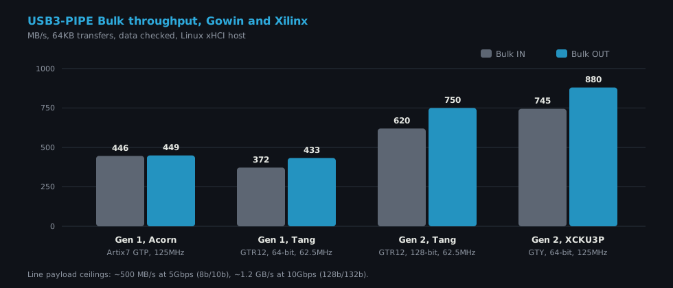
| Tang Mega 138K Pro, GW5AST-138B GTR12, Gen 2x1 (10Gbps) | |
|---|---|
| Enumeration | SuperSpeed Plus Gen 2x1, 10000M |
| Bulk OUT / IN | 749.5 / 619.6 MB/s (128-bit link layer at 62.5 MHz) |
| Full duplex | 522 + 589 MB/s |
| Stability | 3 runs of 4 s per mode, 64KB transfers, data checked: 0 errors, 0 Recovery, 0 LBAD |
On the GW5AST-138B, the 10Gbps design is larger than the 5Gbps one, because of the 80-bit 128b/132b datapaths, the 128-bit link layer and core, and the deeper buffers. Measured with Gowin 1.9.12.04, lean bench design (Gen 1 and Gen 2 PHY, 128-bit core, Bulk bench endpoints), timing met: tx 125.1, rx 125.1, sys 63.3 MHz:
| Logic (LUT + ALU) | Registers | Block RAM | Share of the GW5AST-138B | |
|---|---|---|---|---|
| Complete design, Gen 2x1 | 47,475 | 29,385 | 113 BSRAM | 35% logic, 22% registers, 34% block RAM |
This is more than twice the LUT count of the XCKU3P Gen 2 design, which is not surprising: Gowin LUTs have four inputs, Xilinx LUTs six, and the Tang moves twice as many bits per cycle at half the clock. It still leaves two thirds of the FPGA to the application. It does not fit a 15K LUT part as it is, which is what the next steps are about.
What is not done yet:
- Gen 1 and the 5Gbps fallback on the Tang have not been re-tested since the last aligner fix described below;
- full timing closure only happens on some place and route runs, so
build_best.py-style exploration is still needed; - Gen 2 resources on Gowin have not been optimized at all.
What it gives back#
Most of this work landed in code that every target shares: the link layer, the framing, the CRC, the FIFOs, the core.
The XCKU3P got the same fixes. The Link Command rules are shared with the 64-bit Gen 2 framing on the XCKU3P, and an A/B comparison on the same board showed no regression: 880 MB/s OUT and 745 MB/s IN, as before. The stricter Link Command check also exposed an older bug. A partner aligns its framing on its symbol count, including SKP ordered sets, so after an odd SKP count the next packet is shifted by two symbols. The Gen 1 RX word aligner applied that shift one word too early and dropped the first symbols of a word. On a link command, one copy was lost. The old rule tolerated it, and the new rule rejected the command and caused a Recovery storm in Gen 1 full duplex, enough to bring down the host controller. A new simulation scenario with random SKP counts at packet boundaries reproduced it, and the fix brought Gen 1 full duplex on the XCKU3P back to 336 + 402 MB/s with zero errors.
The small parts got the timing work. The CRC-32 cascade option and the registered TS generator, checker and TX datapath paths (USB3-PIPE #156) came from this Gen 2 timing work and went straight into the SLogic16U3. There they saved about 500 LUTs and let all five Gowin place algorithms meet timing on a 90% full GW5AT-15.
Lattice ECP5 is back. We dropped ECP5 support in 2022 because it was not stable enough. The separate PIPE clock domain, the half-rate link layer and the restructured datapaths, all built for Gowin, are exactly what the ECP5-5G DCU needed. USB3-PIPE now runs on the LambdaConcept ECPIX-5 with the open source toolchain (Yosys, nextpnr, Trellis) at 431/449 MB/s, and 342 + 349 MB/s in full duplex (#171).
The next analyzer. A 10Gbps logic analyzer like the SLogic32U3 needs exactly this: Gen 2 on a GTR12, on a fabric where every level counts. The next step is making the 10Gbps stack small enough for that kind of device, the same way the 5Gbps stack was cut down for the SLogic16U3.
The work is merged: USB3-PIPE #154 (the GTR12 at 10Gbps, rate change, Gen 2 with the split clocking) and #158 (128-bit link layer, robustness, timing).
Try it#
# USB3-PIPE at 10Gbps on the Tang Mega 138K Pro (Gowin IDE 1.9.12, SFP2USB adapter in SFP0,
# USB 3.2 Gen 2 host port).
git clone https://github.com/enjoy-digital/usb3_pipe && cd usb3_pipe
pip3 install -e .
./bench/sipeed_tang_mega_138k_pro.py --build --example bench --lean \
    --gen2-capable --refclk 125M --pll CPLL --link-words 4 --place-option 2 --route-option 0
openFPGALoader -c ft2232 build/sipeed_tang_mega_138k_pro/gateware/impl/pnr/project.fs
lsusb -t   # 10000M
./bench/usb3_bench.py both --transfer-size 65536 --csr-csv build/sipeed_tang_mega_138k_pro/csr.csv

# The 10Gbps link in simulation: 128-bit link layer, full duplex stress, Recovery mid-traffic.
./sim.py --gen2 --dev-pipe-cd --gen2-data-width 80 --link-words 4 --host-burst-duplex 64
./sim.py --gen2 --dev-pipe-cd --gen2-data-width 80 --link-words 4 --host-recovery-mid
Thanks to Sipeed for the Tang Mega 138K Pro and the board photo. The 10Gbps lane configuration started from the LiteEth GW5 10GBASE-R work.
Work and ideas by Enjoy-Digital; written up with AI in the loop.