
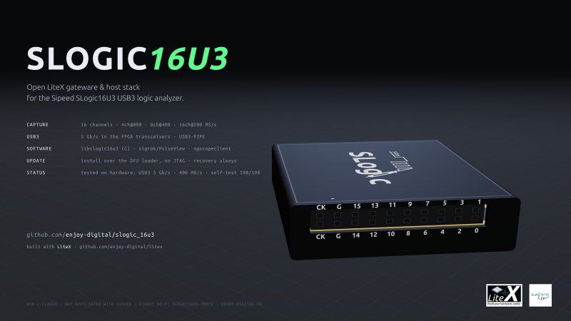
TL;DR: The Sipeed SLogic16U3 is a small USB 3 logic analyzer with no USB chip: the GTR12 transceiver of its Gowin GW5AT-15 drives the USB-C connector directly. That made it a fun target and a demanding one for USB3-PIPE, our USB 3 device in the FPGA fabric, and it is the reason we ported USB3-PIPE to Gowin. The result is SLogic16U3 LiteX, an open alternative bitstream and host stack. It has 16 channels at up to 800 MS/s and 400 MB/s sustained over USB 3, with every sample checked by a built-in self-test. It works with sigrok/PulseView and ngscopeclient, installs over USB without opening the case, and the stock firmware can always be restored. A first beta is released.
Why this analyzer#
USB 3 logic analyzers usually pair an FPGA with a USB 3 controller such as Cypress’ FX3, which costs $20 to $30 on its own. Sipeed’s SLogic16U3 sells for about $69 and has no USB chip. Its GW5AT-15, a 15K LUT Gowin FPGA, has one GTR12 transceiver quad, and lane 0 goes to the USB-C connector through a Type-C lane mux.
For USB3-PIPE, it is close to an ideal stress test:
- a real product with a hard requirement. At 16 channels and 200 MS/s, or 4 channels at 800 MS/s, the analyzer produces 400 MB/s. That is 80% of what a 5Gbps link can carry, and the stream cannot pause: if the host falls behind, samples are lost;
- a small FPGA. The USB 3 stack has to share 15K LUTs with the capture engine;
- a fabric and a toolchain we had never used for USB 3. Until then, USB3-PIPE only ran on Xilinx devices, where it had plenty of margin.
So the SLogic16U3 is what motivated the Gowin port. We did it in two steps. First the Tang Mega 138K Pro, a large GW5A with room for debug logic, then this board, where every LUT counts.
It is also a fun project: a logic analyzer where every layer is open, from the USB 3 PHY to PulseView, is a satisfying thing to have on the bench.
The hardware#
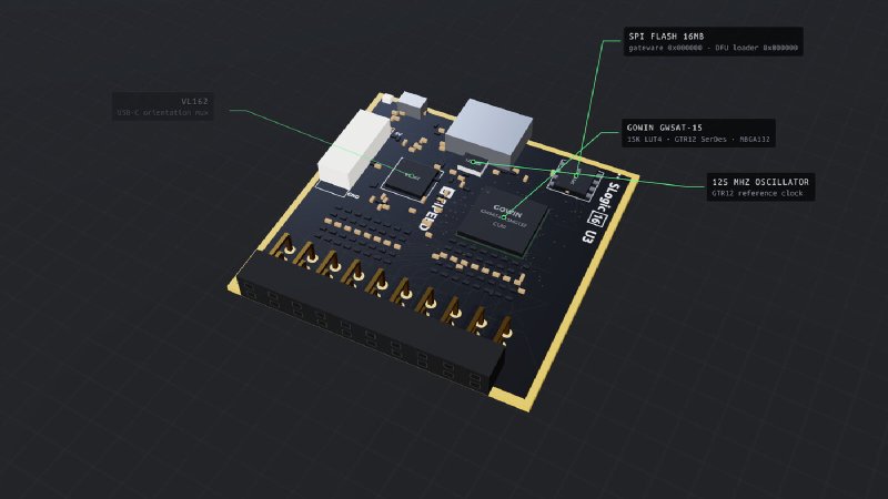
There is no public schematic, so the pinout had to be reversed. We started that in December 2025: the Gowin build and load flow first, then a bitstream toggling
every IO bank to find the pins one by one. The UART TX came first, then the logic analyzer inputs.
The result went into LiteX-Boards as the
sipeed_slogic16u3 platform and target, where other projects could pick it up. The
slogic16u3-trace project, which turns the analyzer
into an ARM/RISC-V trace receiver, reused it and went further: the complete input mapping, the DFU
loader protocol and the flash layout. We now reuse that in turn, and this project completed the
LiteX-Boards platform with what it found (LED, oscillator enable, multiboot). That is the nice part
of open source: release what you have, let others extend it, and everyone benefits from each other’s
work. The rest comes from Sipeed’s libsigrok driver for the stock register protocol, and from our own
checks:
- 16 inputs behind dividers of about 0.47, with a threshold of about 0.75 V at the FPGA pins, so about 1.6 V at the connector. The stock firmware makes the threshold adjustable through a DAC. Our gateware keeps the fixed default for now;
- one accurate clock: a 125 MHz oscillator that only reaches the GTR12 reference input. There is no fabric clock input, so the sample clock is derived from the transceiver TX clock. Otherwise only the internal oscillator, which is not accurate, is available;
- a 16MB SPI Flash: the application bitstream at 0, Sipeed’s DFU loader at 8MB. The loader is a golden image: the MODE button, or a bitstream that fails its check, brings the FPGA back to it;
- USB 2.0 in the fabric: the GW5AT-15 has no hard USB 2.0 PHY, but the USB-C D+/D- lines reach FPGA pins (comparator inputs, a D+ pull-up control and termination pins). Sipeed’s DFU loader uses them for a soft USB 2.0 High-Speed PHY in the fabric. Our gateware only implements USB 3, so it needs a USB 3 port and cable.
The gateware#
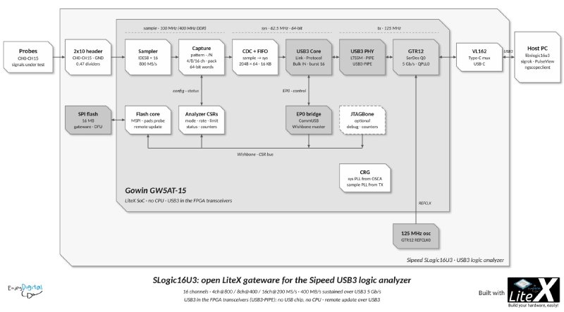
There is no CPU. The host controls everything through EP0, where a USB3-PIPE bridge exposes the SoC’s
Wishbone bus, compatible with LiteX’s litex_server --usb. The samples stream on a Bulk IN endpoint.
- Sampler: one IDES8 deserializer per input, clocked at 400 MHz DDR from a PLL on the GTR12 TX clock. That gives 8 samples per 100 MHz cycle: an 800 MS/s base rate.
- Capture: decimation by any N, 4, 8 or 16 channel modes, packing into 64-bit words, sample-exact limits and overflow detection. It also has two test sources: a counter and a pattern generator with UART, SPI, PWM, clock and Gray counter signals.
- CDC and FIFO: 64-bit words cross from the 100 MHz sample domain to the 62.5 MHz system domain. At 32 bits, the crossing was limited to 250 MB/s.
- USB 3: the USB3-PIPE PHY and device core, with the PIPE at 125 MHz on the GTR12 clock and the rest at 62.5 MHz on 64-bit words, as on the Tang.
- Flash: an SPI engine that updates the application region from the host.
| Channels | Max sample rate | Bandwidth |
|---|---|---|
| 4 | 800 MS/s | 3.2 Gb/s |
| 8 | 400 MS/s | 3.2 Gb/s |
| 16 | 200 MS/s | 3.2 Gb/s |
Simulation first, then one day of hardware#
The project followed the loop we use everywhere now: implement, simulate, build, test on hardware with a script, document, commit. Most of it was done before the board was ever plugged in. The cores were tested against reference models in Migen. A system simulation connected USB3-PIPE’s USB 3 host model, the device core and the same SoC as the hardware target, and ran CSR accesses and captures over Bulk IN. On the host side, the C library has a simulated device that follows the gateware registers and packing, so the tools, the sigrok driver and the ngscopeclient bridge were tested end to end without hardware.
The repository started on 29 October with the gateware cores, the SoC, the system simulation and the complete host stack, all in simulation. Hardware bring-up was on 30 October:
- around midday: USB 3 enumeration at 5Gbps, with EP0 CSR accesses 1000/1000. The self-test passed up to 200 MB/s;
- early afternoon: 400 MB/s sustained over 30 s in all three channel modes;
- evening: install and restore over the DFU loader, then a first beta release.
The USB 3 bring-up findings are in the Gowin post. Briefly:
- the GTR12 needed QPLL0 and Gowin’s own CDR value instead of the generated one;
- GowinSynthesis put a FIFO with an asynchronous read into block RAM, so every control request read back as zeros;
- the AMD xHCI host only reached 400 MB/s Bulk IN with a Max Burst of 16 instead of 8.
Each finding went back into USB3-PIPE, LiteICLink or LiteX-Boards rather than staying in this project.
Fitting in 15K LUTs#
The USB 3 PHY and device core alone take about 70% of the GW5AT-15 logic. The capture engine, the flash core and the control logic bring the total to about 90%. With Gowin 1.9.12.04:
| Build | Logic | BSRAM | sys (62.5 MHz) | tx (125 MHz) | sample (100 MHz) |
|---|---|---|---|---|---|
| Full design, release 0.1 | 13,222 (88%) | 34/35 | 74.7 MHz | 131.5 MHz | 101.8 MHz |
| With the hardware trigger | 13,823 (92%) | 34/35 | 75.9 MHz | 143.9 MHz | 106.4 MHz |
| With the trigger and outputs | 13,759 (91%) | 34/35 | 78.4 MHz | 163.6 MHz | 124.8 MHz |
At this fill level, timing is fragile. Gowin’s place and route has no seed. Its results are
deterministic for a given netlist, but they change with any netlist change. build_best.py builds
each of the five place algorithms with two route algorithms in parallel and keeps the best result.
At first, only some of them met timing. They all do now, and the later builds, with more features,
also have more margin. These changes made the difference:
- USB3-PIPE: a cascaded CRC-32 option, about 500 LUTs smaller, and registered TS generator, checker and TX datapath paths (#156), a registered EP0 Wishbone bus;
- datapath registers without reset: the sample reset had a fanout of about 1250, now a few hundred, which reduced routing congestion;
- capture: the number of kept samples comes from a table, and the limit decision is off the 48-bit counters.
Testing without probes#
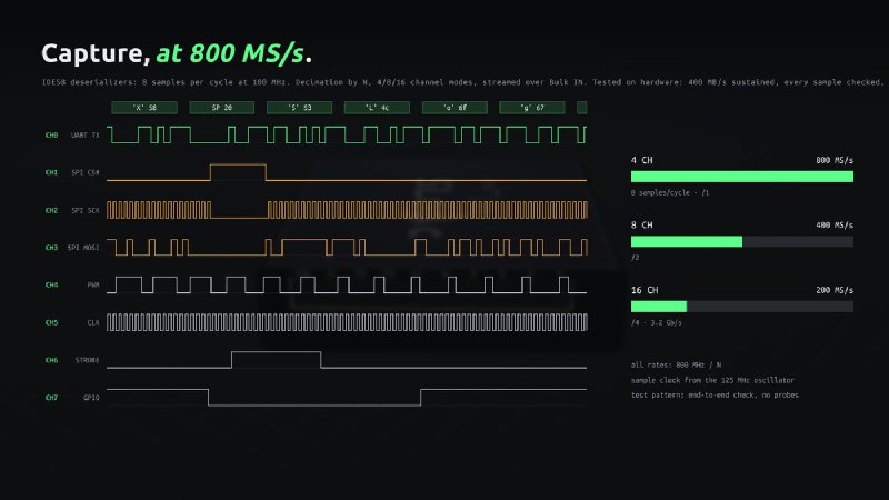
A logic analyzer that drops or reorders a sample is worse than none, so the gateware checks itself. The capture can take its data from a counter or from a pattern generator that runs at the base rate after the deserializers. The generator outputs a UART at 1 Mbaud, SPI at 12.5 MHz, a PWM with a duty cycle sweep, a 100 MHz clock and a Gray counter. It restarts with each capture, and the host library has the same model.
slogic16u3_util check runs both sources in every channel mode and at sample rates from 1 kHz to
the maximum, and checks every sample: 198/198 on hardware. slogic16u3_util bench measures the
sustained rate: 400 MB/s over 30 s at 4 channels at 800 MS/s, 8 at 400 MS/s and 16 at 200 MS/s. The
generator signals also decode in sigrok, which checks the whole path from the gateware to the
protocol decoders. The test sources come after the IDES8, so the inputs themselves need real
signals. That is next on the list.
The host side#
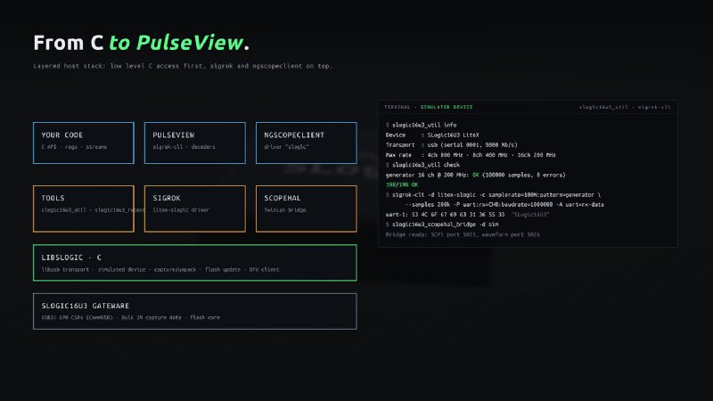
The host stack is layered, with C first:
- libslogic16u3: USB 3 transport on libusb (EP0 CSR accesses, a ring of Bulk IN transfers), the simulated device, the flash and DFU clients;
- tools:
slogic16u3_util(info, check, bench, flash, DFU) andslogic16u3_record, which writes raw, VCD or CSV; - sigrok/PulseView: a native libsigrok driver,
litex-slogic, with a build script for libsigrok, sigrok-cli and PulseView; - ngscopeclient: a TwinLan bridge and a scopehal driver.
Adding -d sim to the tools or conn=sim to sigrok runs everything on the simulated device. That
is how the drivers were developed, and how their end-to-end tests run.
Install without JTAG, restore anytime#
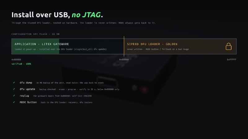
Replacing an instrument’s firmware should not be scary. The Sipeed DFU loader is never written: the tools only write the application region below 8MB. Installation goes through that loader, over USB, without opening the case:
- press MODE: the analyzer re-enumerates as the DFU loader;
dfu dumpbacks up the whole 16MB Flash, read twice and compared;dfu updatechecks that the backup belongs to this unit, then erases, programs and verifies the application region in about 36 s;- replug on a USB 3 port, and
slogic16u3_util check.
dfu restore puts the stock firmware back from the backup. One practical detail: the loader runs
USB 2.0 in the FPGA fabric, and it is marginal on some host ports. Going through a USB 2.0 hub
fixes it, and the DFU client retries lost transfers.
Status#
Release 0.1 beta has the gateware, the Linux tools, the udev rules and an install guide. Tested on hardware: USB 3 at 5Gbps, 400 MB/s sustained in all modes, the self-test, and install and restore over DFU.
So far we have focused on the basic functionality: USB 3, capture, the host stack and a safe install. Next steps:
- real signals on the inputs: channel mapping, and 800 MS/s on 4 channels with real signals;
- an adjustable logic threshold, through the DAC that the stock firmware uses;
- a USB 2.0 fallback for USB 2.0 ports and cables. The pins are there, and the soft USB2PHY we wrote for ChromatiX is now in LiteX, but it has to fit in what is left of the FPGA;
- remote updates from the running gateware, which need the Flash pins probed first;
- the hardware trigger (edge, level and pattern, with a pre-trigger window in the capture FIFO) and the outputs (trigger out, multi-unit sync, a loopback self-test of the inputs) work in simulation and are next on hardware.
The Gowin IDE is still required to build the gateware. Everything else is open source.
What comes next#
The SLogic16U3 pushed USB3-PIPE onto Gowin and onto a small part, and it improved the core for every target. Sipeed’s next analyzer, the SLogic32U3, is a 10Gbps USB 3.2 Gen 2 device. We have started preparing for that class of hardware with 10Gbps on the Tang Mega 138K Pro.
Try it#
# Release package (Linux x86_64 tools, gateware, udev rules, INSTALL.md).
tar xf slogic16u3-0.1.0.tar.gz && cd slogic16u3-0.1.0 && sha256sum -c SHA256SUMS
sudo cp udev/99-slogic16u3.rules /etc/udev/rules.d/ && sudo udevadm control --reload-rules
export PATH=$PWD/tools/linux-x86_64:$PATH
# MODE button: DFU loader (LED blinking red).
slogic16u3_util dfu dump slogic16u3-backup.bin       # keep it: your way back to stock.
slogic16u3_util dfu update gateware/slogic16u3-0.1.0.bin --backup slogic16u3-backup.bin
# Replug on a USB 3 port.
slogic16u3_util info && slogic16u3_util check

# From the sources: tests, then the bitstream (Gowin IDE 1.9.12.04).
git clone https://github.com/enjoy-digital/slogic16u3 && cd slogic16u3
python3 -m pytest test && make -C software/user check
./scripts/build_best.py
software/sigrok/build.sh --pulseview          # libsigrok with the litex-slogic driver, PulseView.
software/sigrok/install/bin/sigrok-cli -d litex-slogic -c samplerate=100M --samples 1M -P uart:rx=CH0 -A uart
Thanks to Sipeed for the hardware and the DFU loader, which makes all of this safe to try. The slogic16u3-trace project extended our first pinout work and documented the input mapping, the DFU protocol and the flash layout. Kenta Ida wrote the first open USB 3 stack on the SLogic16U3. This project is not affiliated with Sipeed.
Work and ideas by Enjoy-Digital; written up with AI in the loop.