The 1 MHz problem#
If you build FPGA SoCs, you know the simulation tax. You change one register in a peripheral, start Verilator, and then you wait. Not for your peripheral, but for the CPU. Verilator simulates every gate of the RISC-V core while it boots, sets up a stack, runs the BIOS and parses a boot prompt, all at roughly one simulated megahertz, before it ever touches the thing you actually changed.
So most of the time I spend “in simulation” isn’t spent on my design. It’s spent waiting for a CPU I’m not even debugging. 😅
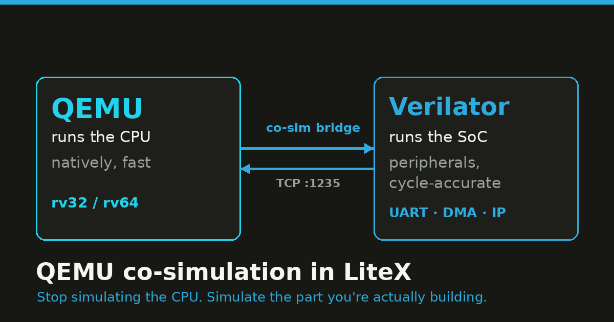
PR #2468 takes the shortcut: don’t simulate the CPU. Run it in QEMU at native speed, and keep simulating the SoC (the interconnect and the peripherals) in Verilator. Each tool does the part it’s good at, and the two talk over a small bridge.
What the PR adds#
The split is simple:
- QEMU owns the CPU. The RISC-V core, its local ROM/RAM, the RISC-V timer and software interrupts (ACLINT/CLINT) and the PLIC all live inside QEMU and run at native speed.
- Verilator owns the SoC. The LiteX interconnect and every peripheral (UART, Ethernet, whatever IP you’re working on, DMA) is simulated cycle-accurately, exactly as before.
Whenever the CPU in QEMU touches an address that belongs to the LiteX SoC (a CSR, that is a control/status register, a peripheral buffer, or shared main RAM), QEMU forwards the access over a TCP bridge to the Verilator side, which turns it into a real Wishbone/AXI bus cycle, lets the SoC react, and sends the result back.

Why it’s faster, and where it isn’t#
A Verilated soft CPU runs at maybe 0.1 to 1 MIPS, because every pipeline stage is simulated. QEMU runs the same code at host speed. The peripherals don’t get any faster (they stay in Verilator, which is the whole point), but the time you used to spend simulating the CPU on every boot, every memcpy, every driver probe is mostly gone.
It’s worth being clear about what this is not. It’s co-simulation, not cycle-accurate CPU verification. The v1 bridge does blocking, single-beat MMIO (no AXI bursts yet), it doesn’t model CPU caches, and exact cycle-level interrupt timing isn’t the goal. If you’re verifying the CPU pipeline, use a Verilated core. If you’re working on the peripherals, drivers and software around the CPU (for me, most of the time), co-simulation is what you want.
Booting the BIOS#
The QEMU CPU shows up as just another --cpu-type. Build the patched QEMU once (it fetches
QEMU v8.2.4, applies the litex-sim machine, and drops the binaries in
build/qemu-litex/bin/):
python3 litex/build/sim/qemu/build_qemu_litex.pyThen run the simulator with qemu as the CPU:
python3 -m litex.tools.litex_sim \
    --cpu-type=qemu \
    --cpu-variant=rv32 \
    --qemu-binary build/qemu-litex/bin/qemu-system-riscv32
LiteX builds the SoC, Verilator compiles it, and once the bridge is listening LiteX starts QEMU pointed at it. Then the familiar banner shows up, except the CPU on the other end is QEMU:
[qemu_wishbone] client connected

        __   _ __      _  __
       / /  (_) /____ | |/_/
      / /__/ / __/ -_)>  <
     /____/_/\__/\__/_/|_|
   Build your hardware, easily!

 (c) Copyright 2012-2026 Enjoy-Digital
 (c) Copyright 2007-2015 M-Labs

 BIOS built on Jun  2 2026 12:03:24
 BIOS CRC passed (ed75e705)

 LiteX git sha1: 01ac04ff5

--================ SoC =================--
CPU:		QEMU RISC-V @ 1MHz
BUS:		wishbone 32-bit data/32-bit addr
CSR:		32-bit data big ordering
ROM:		128.0KiB
SRAM:		8.0KiB

--================ Boot ================--
Booting from serial...
Press Q or ESC to abort boot completely.
No boot medium found

--============== Console ===============--
litex>
Two things to notice. [qemu_wishbone] client connected is the Verilator-side bridge module
reporting that QEMU has connected. And QEMU runs with -serial none, so there is no QEMU
console. The UART you’re reading is the LiteX UART, simulated in Verilator and reached over
the bridge. The peripheral under test is doing the talking. (@ 1MHz is just the simulated
SoC clock; the CPU itself runs as fast as QEMU likes.)
A first benchmark#
The prompt is nice but it doesn’t show the speed-up: a tiny BIOS boots fast either way. So let’s make the CPU work: give the SoC some main RAM and let the BIOS run its memory test, which is a tight read/write loop, exactly the kind of CPU-bound code a Verilated core struggles with.
Same SoC, same BIOS, same 2 MiB of main RAM. Only the CPU implementation changes.
# CPU in QEMU (peripherals + RAM still in Verilator, via the shared-RAM file)
python3 -m litex.tools.litex_sim --cpu-type=qemu --cpu-variant=rv32 \
    --qemu-binary build/qemu-litex/bin/qemu-system-riscv32 \
    --integrated-main-ram-size=0x200000

# CPU simulated cycle-by-cycle in Verilator
python3 -m litex.tools.litex_sim --cpu-type=vexriscv \
    --integrated-main-ram-size=0x200000
Timing the wall-clock between Memtest at 0x40000000 (2.0MiB)... and Memtest OK:
| CPU implementation | 2 MiB BIOS memtest (wall-clock) | Speed-up |
|---|---|---|
| QEMU co-simulation | ~0.15 s | ~100× |
| VexRiscv in Verilator | ~15.3 s | 1× (baseline) |
The BIOS memspeed numbers say the same thing from the other side: 285.7 MiB/s write /
400.0 MiB/s read with QEMU, versus 1.6 MiB/s write / 918.9 KiB/s read on the Verilated core.
Same SoC, same machine; the only difference is who executes the instructions.
One detail: in the QEMU run, main RAM is a shared file (memory-backend-file) mapped by both
QEMU and Verilator, so a DMA-capable peripheral in Verilator and the CPU in QEMU see the same
bytes. The peripheral side stays accurate; only the CPU sped up. 🚀
How the bridge works#
The protocol is small. QEMU opens one TCP connection and does one blocking request at a time. Every message is a fixed 32 bytes, little-endian:
| Offset | Field | Size | Meaning |
|---|---|---|---|
| 0 | magic | 4 | 0x3051584c (LXQ0) request / 0x3052584c (LXR0) response |
| 4 | version | 2 | 1 |
| 6 | op | 2 | 0 read · 1 write · 2 IRQ poll |
| 8 | size | 4 | 1, 2, 4, 8 (or 0 for an IRQ poll) |
| 16 | addr | 8 | byte address |
| 24 | data | 8 | write data / read data |
When the CPU reads or writes an address in the LiteX MMIO window, QEMU sends a READ/WRITE
and the Verilator-side qemu_wishbone module runs a real bus cycle, replying with the data
plus the current LiteX interrupt bitmask. The IRQ poll (op=2) lets a LiteX interrupt reach
the CPU even when it isn’t otherwise touching the bus.
The memory map follows the same split. This is the command LiteX builds and launches for you (rv32):
qemu-system-riscv32 -M litex-sim,xlen=32,\
  bridge-host=127.0.0.1,bridge-port=1235,\
  bridge-base=0x80000000,bridge-size=0x80000000,\
  reset-addr=0x0,rom-base=0x0,sram-base=0x10000000,main-ram-base=0x40000000,\
  clint-base=0xf0010000,plic-base=0xf0c00000,csr-base=0xf0000000,... \
  -m 67108864B -nographic -serial none -monitor none \
  -bios build/sim/software/bios/bios.bin
ROM, RAM, CLINT and PLIC are QEMU-local (fast). Everything in the bridge-base/bridge-size
window (CSRs, LiteEth buffers, a framebuffer) is forwarded to Verilator. You don’t write any
of that command; LiteX does.
QEMU is just another CPU#
None of this needed special-casing in the SoC code, and that’s the part I find satisfying.
In LiteX a CPU is an abstraction: a Python class that inherits from a common CPU base,
declares a few attributes (family, variants, register width), and exposes one or more bus
masters to the SoC. VexRiscv does it, Rocket does it, NaxRiscv, CVA6 and PicoRV32 do it. Even
the hard cores do it: the Zynq and ZynqMP processing systems are LiteX CPU types too. The
integration code doesn’t care what’s behind the bus master; it wires it into the interconnect
like any other.

Making QEMU “a CPU” is the same job. Here’s the core of litex/soc/cores/cpu/qemu/core.py,
trimmed down:
class QEMU(CPU):
    category   = "emulator"
    family     = "riscv"
    name       = "qemu"
    human_name = "QEMU RISC-V"
    variants   = ["standard", "rv32", "rv64"]

    def __init__(self, platform, variant="standard"):
        # Pick the bus standard the SoC asked for...
        self.bus_standard = _get_qemu_bus_standard(platform)   # wishbone / axi-lite / axi
        self.bus          = _qemu_bus_interface(self.bus_standard)

        # ...and present it to the SoC as a regular bus master.
        self.periph_buses = [self.bus]
        self.memory_buses = []

        self.interrupt = Signal(32)
        self.reset     = Signal()
        ...
No Verilog, no pipeline. The class hands the SoC a Wishbone (or AXI-Lite, or AXI) master, an interrupt vector and a reset line, and the simulation glue connects that master to the external QEMU process through the bridge module.
From the SoC’s side there’s nothing special about it. The build log brings QEMU up exactly the way it would a soft core:
INFO:SoC:CPU qemu added.
INFO:SoC:CPU qemu adding IO Region 0 at 0x80000000 (Size: 0x80000000).
INFO:SoC:CPU qemu setting reset address to 0x00000000.
INFO:SoC:CPU qemu adding Bus Master(s).
INFO:SoCBusHandler:cpu_bus0 added as Bus Master.
INFO:SoC:CPU qemu adding SoC components.
INFO:SoCBusHandler:clint Region added at Origin: 0xf0010000 ...
INFO:SoCBusHandler:plic  Region added at Origin: 0xf0c00000 ...
A whole emulator gets added the same way as a 2000-LUT soft core, because in LiteX a CPU is a contract, not a block of HDL.
This looks a lot like Zynq and SoC FPGAs#
If the shape feels familiar, it should. A Xilinx Zynq / Zynq MPSoC, or an Intel/Altera SoC FPGA, is a hardened processing system (the Arm complex, its caches, its DDR controller, all fixed silicon) next to programmable fabric where you build your peripherals. You don’t redesign the CPU; you build around it. That’s the same picture as the diagram above, with the hardened PS sitting in the slot where QEMU sat.
So the same way of working carries over: model the hardened PS with an emulator, simulate your fabric peripherals cycle-accurately, and bring up the drivers and software against the pair, with the visibility of simulation, before or alongside real hardware. Whether the “hard” part is a QEMU process or a vendor PS, the rest of the SoC doesn’t care.
Booting Linux#
A BIOS is a warm-up. The reason I wanted this is bigger software. The
linux-on-litex-vexriscv project can
already boot Linux in the LiteX simulator, and if you’ve run ./sim.py there and watched a
Verilated VexRiscv-SMP work through OpenSBI and a kernel decompress, you know it takes a
while. Booting an OS is hundreds of millions of instructions; at ~1 simulated MHz, that’s the
go-get-a-coffee range.
So let’s boot a real rv64 Linux with the kernel in QEMU and its console coming out of the LiteX UART in Verilator:
python3 -m litex.tools.litex_sim \
    --cpu-type=qemu --cpu-variant=rv64 \
    --qemu-ram-size=0x10000000 \
    --qemu-binary   build/qemu-litex/bin/qemu-system-riscv64 \
    --qemu-firmware .../opensbi-riscv64-generic-fw_dynamic.bin \
    --qemu-kernel   .../Image \
    --qemu-dtb      .../litex-sim-rv64.dtb
QEMU owns the CPU, RAM and the RISC-V local-interrupt machinery Linux expects (the ACLINT/CLINT
timer and the SiFive-compatible PLIC); OpenSBI is the stock generic build. The device tree
describes those plus one Verilator-side peripheral, the litex,liteuart console at
0x12001800, which sits in the bridge window. So every byte Linux prints goes CPU → bridge →
Verilator → your terminal:
OpenSBI v1.3.1
Platform IPI Device       : aclint-mswi
Platform Timer Device     : aclint-mtimer @ 1000000Hz
Boot HART Base ISA        : rv64imafdch
[    0.000000] Linux version 5.11.0 ... (riscv64 ... GCC 13.4.0) ...
[    0.000000] earlycon: liteuart0 at MMIO 0x0000000012001800 (options '')
[    0.000000] printk: bootconsole [liteuart0] enabled
[    0.000000] Kernel command line: console=liteuart rdinit=/init earlycon
[    0.000000] Memory: 176352K/260096K available ...
[    0.114190] devtmpfs: initialized
[    0.405614] 12001800.serial: ttyLXU0 at MMIO 0x0 ... is a liteuart
[    0.419278] printk: console [liteuart0] enabled
[    0.535703] Freeing unused kernel memory: 2092K
[    0.543183] Run /init as init process
========================================================
[init] Hello from Linux userspace!
[init] CPU executed by QEMU, peripherals by Verilator.
[init] This console is the LiteX UART (liteuart), reached
[init] through the QEMU <-> Verilator co-simulation bridge.
========================================================
That liteuart line is the point: OpenSBI and Linux are both talking through a
Verilator-simulated peripheral, over the bridge, while the CPU runs at QEMU speed. From the
OpenSBI banner to the /init prompt was about 1.3 seconds of wall-clock. 🐧
For comparison: the same boot is hundreds of millions of instructions, and the Verilated VexRiscv runs ~100× slower than QEMU on the same SoC (that’s the memtest number from earlier), which puts a cycle-simulated boot in the many-minutes range. A second or so versus several minutes is the difference between iterating on a driver and waiting on one.
A note on reproducibility, since I’d rather be honest about it: this is a real boot from my
machine, but getting there meant extending the PR. The litex-sim machine originally only
loaded a -bios; I added the usual virt-style -kernel/-dtb loading
(riscv_load_firmware / riscv_load_kernel / riscv_load_fdt plus the reset vector) so
OpenSBI and a kernel actually boot, wrote the matching rv64 device tree, and added an
earlycon to the in-tree liteuart driver to see early output. Follow-up-commit material,
but the path works end to end today.
What’s next#
This is the first post in a series on LiteX co-simulation, and it’s really the foundation for the fun stuff. A few threads I want to pull on:
- Software CI that actually boots. Wire the QEMU CPU into linux-on-litex-vexriscv so the full boot-to-shell runs in CI in seconds instead of the many minutes a Verilated core needs. Once a boot is that cheap, you can gate every commit on “does the software still come up and pass its tests”, with no FPGA and no overnight simulation.
- More software-modeled peripherals. Today the one peripheral on the bridge is the LiteX UART. Imagine more co-sim modules on the Verilator side: Ethernet bridged to a host TAP, a virtual block device, a framebuffer in a window, fake sensors on I2C/SPI. The drivers get realistic peripherals to talk to, while the CPU stays in QEMU.
- Verilator → real silicon. The PR already has a
qemu_remoteCPU and an Etherbone bridge (litex_qemu_etherbone_bridge.py): same protocol, but the MMIO window is forwarded over Etherbone / PCIe-Bone to a LiteX SoC on an actual FPGA. CPU and software in QEMU on the laptop, peripherals on real hardware. - Debugging and visibility. Where co-simulation really earns its keep:
$displayfrom Verilator, LiteScope captures of the bus, GDB on the software running in QEMU, and waveforms, all at once. Agents make this loop even more useful: see FPGA development with LiteX in the AI era. - Other hacks. Snapshots, fault injection, fuzzing a driver against a deliberately flaky peripheral model… a lot gets easier once the CPU is basically free. :)
The short version: LiteX already treats the CPU as an abstraction, so QEMU slotted in without hacks. What you get back is iteration speed. Stop simulating the CPU, and simulate the part you’re actually building. 🙂
Code: LiteX PR #2468. The LiteX community
is on Discord and #litex on Libera if you want to talk about it.
Work and ideas by Enjoy-Digital; written up with AI in the loop.