

TL;DR: freertos-on-litex runs FreeRTOS
V11.3.0 as the firmware of a LiteX SoC. The kernel is the unmodified upstream submodule; the whole
port is one C file and a one-screen crt0. Every demo is validated end-to-end in litex_sim on a
VexRiscv, no FPGA required, with pytest and CI watching the UART for pass/fail markers, and the
same firmware.bin runs on an Arty A7 without a single source change.
The missing middle#
We have put a fair amount of software on LiteX softcores on this blog: MicroPython and mquickjs at the scripting end, and Linux on 32 MB of HyperRAM at the big end. Between bare-metal C and Linux sits the tier a lot of real products actually ship: the classic small RTOS. Deterministic scheduling, no MMU required, and a kernel measured in kilobytes rather than megabytes.
FreeRTOS is the canonical one: a preemptive scheduler plus queues, semaphores, mutexes, software timers, event groups and task notifications, all in roughly 10 kB of kernel code. A LiteX SoC is a natural target for it. The kernel only needs a small heap, a periodic tick and a UART, the upstream RISC-V port already exists, and VexRiscv provides everything it expects. What was missing was the wiring, and the point of this repo is that the wiring turned out to be genuinely small.
An unmodified kernel and a thin layer of glue#
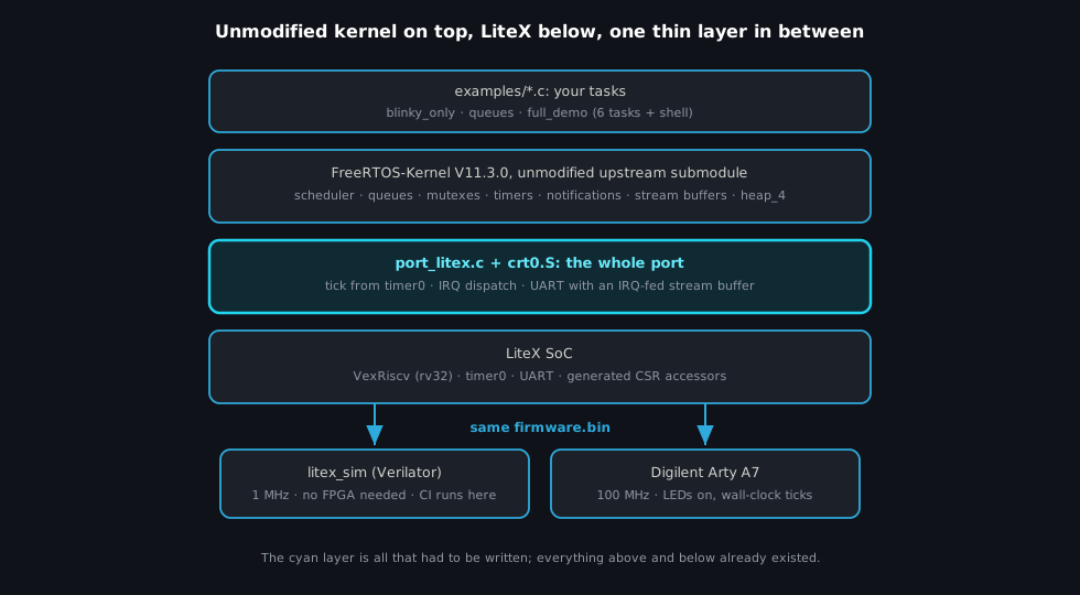
A design rule we set at the start: the FreeRTOS-Kernel submodule stays byte-for-byte upstream,
pinned at V11.3.0. Upstream’s generic RISC-V port asks a board for exactly three things:
- A chip-specific extensions header. VexRiscv “standard” has no CLINT, no
mtimeand no FPU, so theRISCV_no_extensionsvariant applies as-is. - An interrupt handler. With no
mtime, upstreamportASM.Shands every asynchronous interrupt to one C function, and that function is where LiteX plugs in: read the pending mask from LiteX’s IRQ CSRs and dispatch to the peripherals that raised it. - A tick source. A weak
vPortSetupTimerInterruptthat programs whatever periodic timer the platform has. Here that is LiteX’stimer0, in countdown-and-reload mode:
// firmware/port_litex.c
void vPortSetupTimerInterrupt(void)
{
    /* Disable while reprogramming. */
    timer0_en_write(0);
    timer0_load_write(TICK_RELOAD);
    timer0_reload_write(TICK_RELOAD);
    timer0_en_write(1);

    /* Clear any stale event, enable the "zero" event IRQ. */
    timer0_ev_pending_write(timer0_ev_pending_read());
    timer0_ev_enable_write(1);

    /* Unmask the timer line at the LiteX IRQ controller. */
    irq_setmask(irq_getmask() | (1u << TIMER0_INTERRUPT));
    ...
}
TICK_RELOAD is computed as configCPU_CLOCK_HZ / configTICK_RATE_HZ, and configCPU_CLOCK_HZ
comes straight from the CONFIG_CLOCK_FREQUENCY constant LiteX generates. The same source gives a
correct 1 kHz tick at 1 MHz in simulation and at 100 MHz on a board.
The LiteX side of all this is firmware/port_litex.c (under 400 lines including its comments)
plus a crt0 that fits on one screen: set the stack pointer, point mtvec at the FreeRTOS trap
handler, clear .bss, enable machine external interrupts, call main(). Because upstream
portASM.S already saves and restores the full register context around the handler, the LiteX
interrupt dispatch is ordinary C: no interrupt attributes, no hand-written register shuffling.
The UART is the one place where the port deliberately steps around LiteX’s libbase: instead of
uart_init() and its own ISR dispatcher, the port keeps a polling TX path (the 16-byte FIFO at
115200 baud drains fast enough that busy-waiting never measurably stalls a task) and an IRQ-driven
RX path that pushes bytes into a FreeRTOS stream buffer. The shell task blocks on
xStreamBufferReceive() with an infinite timeout and consumes zero CPU between keystrokes, which
is the whole point of having an RTOS in the first place. 🙂
Simulation first#
The habit from the AI-era post applies unchanged: before anything runs on a
board, build the feedback loop. Here the loop is litex_sim, and the interesting part is making
it fast enough to live in. LiteX’s default sim flow recompiles the Verilator model on every
invocation, which is fine once and painful the tenth time. The harness splits it in two:
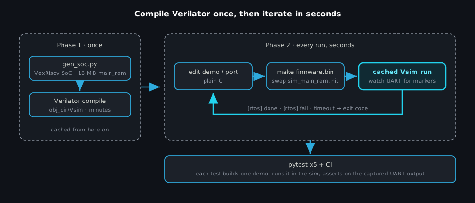
Phase one generates the SoC (VexRiscv, 16 MiB of main RAM, --timer-uptime for the stats
counter) and pays the Verilator compile, a couple of minutes. Phase two is the loop you actually
live in: rebuild firmware.bin, convert it to the memory-image file the simulator loads at
reset, and relaunch the cached model. Seconds per iteration.
Every demo prints a [rtos] done or [rtos] fail marker when it finishes, and the harness turns
those into exit codes. On top of that sit five pytest tests, each building one demo and asserting
on the captured UART output, and CI runs the whole matrix on every push. Firmware tested like
gateware.
The full demo#
full_demo is the kitchen-sink example: six tasks and a software timer exercising queues, a
mutex, task notifications with timeouts, and the IRQ-fed stream buffer, with a small interactive
shell on the UART. A run looks like this:
--========= freertos-on-litex =========--
FreeRTOS:        V11.3.0    heap: 65536 bytes
CPU:             VexRiscv @ 1000000 Hz   tick: 1000 Hz
Demo:            full_demo

[shell] ready. type 'help' for commands.
[display] t=0.309s  samples=2  temp=19.20C  press=1013.2 hPa
[display] t=0.608s  samples=5  temp=19.53C  press=1012.9 hPa
---- run-time stats ----
dispctl         13726           <1%
IDLE            678678          25%
sensor_p        103713          3%
sensor_t        87688           3%
blinky          28494           1%
fusion          184465          6%
watchdog        43583           1%
shell           37151           1%
Tmr Svc         1042822         38%
---- heap free: 44960 / 65536 bytes
[rtos] done
The run-time stats percentages come from LiteX’s --timer-uptime 64-bit cycle counter, which is
exactly the free-running clock configGENERATE_RUN_TIME_STATS wants. The shell understands
help, tasks, heap, uptime, stop and reboot (reboot writes LiteX’s ctrl_reset CSR,
so the whole SoC restarts). The demo self-terminates after a bounded number of display cycles so
that unattended CI runs always reach a marker; --keep-running keeps the shell alive for humans.
The same binary on a real board#
The firmware never asks whether it is running under Verilator or on silicon. Hardware bindings go through the CSR accessors LiteX generates, and each one is guarded:
#if defined(CSR_LEDS_BASE)
    leds_out_write(pattern);   /* Arty: 4 LEDs; sim: not instanced, skipped. */
#endif
So the identical firmware.bin runs against the minimal simulated SoC and against a Digilent
Arty A7 build with LEDs and switches. On the Arty at 100 MHz the only visible difference is that
time is real: a 500 ms vTaskDelay takes 500 ms instead of several seconds of simulated 1 MHz
patience, and the blinky pattern shows up on actual LEDs.
Try it#
No hardware needed for the first run:
git clone --recursive https://github.com/enjoy-digital/freertos-on-litex
cd freertos-on-litex
./sim/gen_soc.py      # one-time SoC generation + Verilator compile
./sim/run_sim.py      # build and run the default full_demo
Then ./sim/run_sim.py --demo blinky_only for the smallest possible example,
--demo queues for the producer/consumer pattern, --send "tasks" to drive the shell from the
command line, and pytest -v for the whole test suite. For a real board,
docs/hardware.md
walks through the Arty A7 flow: build the SoC, make the firmware against it, load with
litex_term.
Where this fits in the lineup: if the task needs a filesystem, networking stacks and processes,
Linux is a make.py away. If it needs an interactive REPL and quick
scripting, MicroPython is there. And when it needs five tasks with
deterministic priorities in 80 KiB of RAM, this is the missing rung on the ladder, and it is a
thin one to stand on.
Built on LiteX and FreeRTOS (the kernel is the unmodified upstream FreeRTOS-Kernel, MIT licensed; everything in the repo itself is BSD-2-Clause, like LiteX).
Work and ideas by Enjoy-Digital; written up with AI in the loop.