TL;DR: during COVID I turned a $15 ColorLight LED-panel board (ECP5) into a small LiteX SoC with Ethernet and a couple of GPIOs, wired a cheap relay module to it, and used it to power-cycle a PC in the office from home. Built entirely with the open-source Yosys/NextPnr toolchain. At the end: the trick I use to reverse-engineer an unknown board from the FPGA side.
The problem, in 2020#
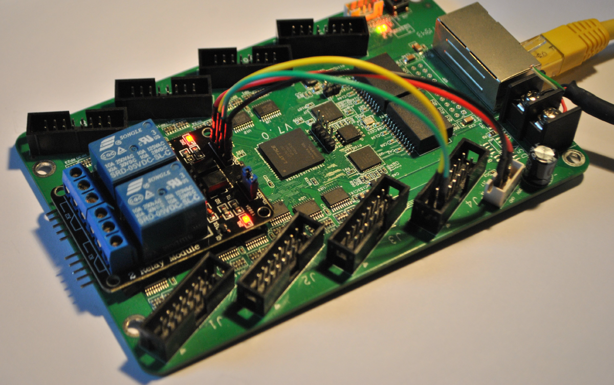
This one is a few years old. Back in the strange early-COVID days I needed to power a machine in the office on and off from home, and I really did not want to drag all the lab gear back to the flat. I had a pile of $15 ColorLight LED-panel boards on the desk. They are meant to drive big RGB LED matrices, but under the hood they are a perfectly good little FPGA board: a Lattice ECP5, a Gigabit Ethernet PHY, SDRAM, SPI flash, and rows of HUB75 connectors I could use as GPIO.
So I put a LiteX SoC on one, gave it Ethernet, and wired a two-channel relay module across the PC’s power and reset buttons. Could I have done this with a Raspberry Pi or an ESP32 for about the same money? Of course. But the fun was doing it with our own tools, on a board that costs less than lunch, with a fully open-source FPGA flow.

A $15 board and a fully open toolchain#
The board is a ColorLight 5A-75B (an LFE5U-25F ECP5). The nice part is that the entire build uses
open-source tools: Yosys for synthesis, NextPnr for place-and-route, and Project Trellis for the
ECP5 bitstream. No vendor login, no license server.
At the time, the ColorLight boards were not supported in litex-boards yet, so adding the platform
and a target for them was part of the project. That turned out to be one of the more useful
outcomes: the support written then is still in litex-boards today, and these boards have since
become a popular cheap way into open-source FPGA work.
The SoC#
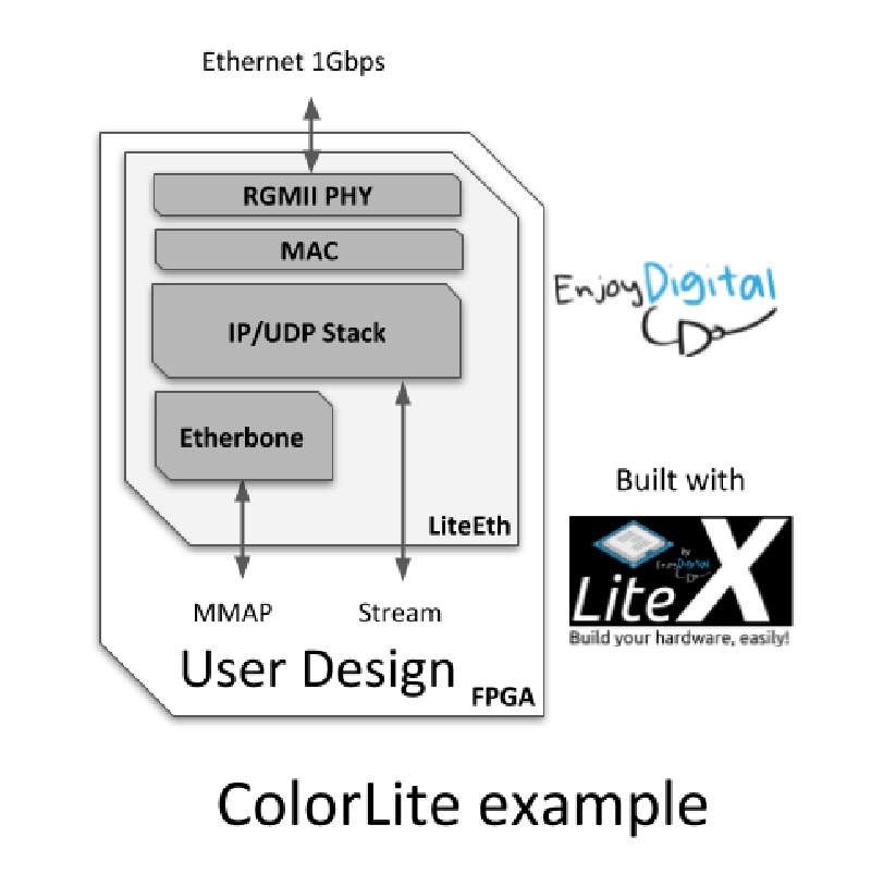
It is a SoCMini with three things bolted on: a LiteEth RGMII PHY plus Etherbone so I can reach
every register over the network, a couple of GPIOs on the HUB75 connector, and a LED chaser
because why not. The core of it is short:
from liteeth.phy.ecp5rgmii import LiteEthPHYRGMII
from litex.soc.cores.gpio import GPIOOut

# Ethernet + Etherbone: every CSR reachable over UDP.
self.ethphy = LiteEthPHYRGMII(
    platform.request("eth_clocks"),
    platform.request("eth"),
    tx_delay = 0e-9)
self.add_etherbone(phy=self.ethphy, ip_address=ip_address)

# GPIO 0 = power switch (short pulse), GPIO 1 = reset switch.
self.gpio0 = GPIOOut(power_sw_gpio)
self.gpio1 = GPIOOut(reset_sw_pads)
LiteEthPHYRGMII is the LiteEth ECP5 RGMII PHY: getting Gigabit Ethernet up on a cheap Lattice
part is one import and a tx_delay you tune in the 0 to 2 ns range for your board revision.
add_etherbone then exposes the whole SoC bus over UDP, so the relay GPIOs (and the SPI flash, and
anything else) are reachable with a Python script from my laptop.
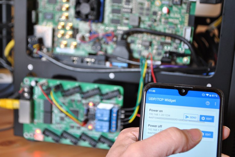
Driving it from home#
Build and flash with the IP you want, then point a LiteX server at it over UDP:
./colorlite.py --ip-address=192.168.1.20 --flash
litex_server --udp --udp-ip=192.168.1.20
After that, the control scripts are tiny RemoteClient programs. The relay module’s two channels
are wired to the R0 and G0 pins of the HUB75 connector, emulating the power and reset buttons,
so:
cd scripts
./test_blink.py       # blink the LED, confirm the link is alive
./test_gpios.py       # toggle the two GPIOs
./test_power_on.py    # short pulse on the power switch
A short pulse on GPIO 0 is a power button press. A longer pulse is a hard power-off. GPIO 1 is the reset line. That is the whole “remote power control” feature: a relay, two pins, and Etherbone.
Reversing a board from the FPGA side#
One more thing, because it is a nice illustration of how flexible LiteX gets when you go off the beaten path. The trick itself is not mine, it is a known way to reverse a board: when you have an FPGA but no schematic and no usable pinout, you can recover the pin map from the FPGA itself, by driving every package ball as a slow bit-banged UART that transmits its own name, then walking the board with a scope or a USB-UART dongle and reading back the name of the pin you touch.
What LiteX adds is how little code that takes. A platform is just Python, so you build the whole thing programmatically. On the ECP5 you do not even need a vendor file: the package pinout comes straight from the open-source Project Trellis IO database. Read it, drop the clock pin, create the platform on the fly, and attach one streamer per ball:
import json

# Package balls straight from the open-source Project Trellis IO database.
ios = list(json.load(open("iodb.json"))["packages"]["CABGA256"].keys())
ios.remove("P6")                       # P6 is the 25 MHz clock, keep it for the PLL

for io in ios:                         # add every ball as a 1-bit output, then stream its name
    platform.add_extension([(io, 0, Pins(io), IOStandard("LVCMOS33"))])
    self.submodules += IOStreamer(io, platform.request(io), sys_clk_freq, baudrate=9600)
IOStreamer is just a small RS232 TX PHY plus a 4-byte ROM holding the ball name, cycled out
forever, so each pin endlessly announces itself:
class IOStreamer(Module):
    def __init__(self, identifier, pad, sys_clk_freq, baudrate=9600):
        phy = RS232PHYTX(...)                                   # 1-bit UART TX on this pad
        mem = Memory(8, 4, init=[ord(c) for c in identifier])  # the ball name
        # ... cycle the four characters out of `pad`, forever ...
Two practical notes from the real sessions:
- The clock. The ColorLight has a 25 MHz crystal on
P6, so the harness runs a PLL off it and excludesP6from the streamed set. If you did not know the clock pin, the ECP5 has an internal oscillator (OSCG) you can fall back on, the same idea as the XilinxSTARTUPE2configuration clock. - Build size. Driving every ball at once is a lot for a small ECP5, so the harness streams the IOs in chunks, walking the package a quarter at a time. On some boards you also hit a pin that halts the gateware when driven; you find it by dichotomy and add it to the excludes.
The point is not the trick, it is that going from an open IO database to a live, self-describing bitstream is a short Python script in LiteX. That is the same flexibility I used to map the ColorLight variants. Slow, but it always works, and it needs nothing but the board and a dongle.
Why I still like it#
It is a small thing, but it is a good snapshot of what LiteX is for, and a compact LiteEth example to point people at: a Gigabit RGMII PHY up, the whole SoC bus exposed over Etherbone, and a useful gadget at the end, in not many lines. A $15 board meant for LED panels became a networked SoC on a toolchain that costs nothing, and it solved a real and slightly silly problem. The obvious next step has been sitting in the README for years: a remote logic analyzer over the Gigabit link. One day. 🙂
A second life: LinuxCNC#
The part I did not expect: the same idea (a cheap Colorlight, LiteX, and Etherbone over Ethernet) turned out to be a great base for open-source motion control, and a small ecosystem of LinuxCNC FPGA cards grew on exactly these boards.
- ColorCNC, the original idea on the LinuxCNC forum: use a Colorlight 5A-75E/5A-75B as the FPGA controller, born from how hard MESA cards were to get hold of. forum thread
- LiteX-CNC by Peter van Tol: a generic LinuxCNC firmware and driver for LiteX-supported FPGA cards, with first-class support for the Colorlight 5A-75B and 5A-75E over Etherbone. GitHub / docs
- Lcnc by faeboli: another LiteX-plus-LinuxCNC combination. GitHub
A lockdown hack to power-cycle a PC became, in other hands, a way to run real machines. That is a good outcome for a $15 board. 🙂
The board is open: github.com/enjoy-digital/colorlite.
Built on LiteX and LiteEth, on a ColorLight 5A-75B with the open-source Yosys / NextPnr / Trellis ECP5 flow.
Work and ideas by Enjoy-Digital; written up with AI in the loop.