TL;DR: The ModRetro Chromatic is a Game Boy handheld
built around a Gowin GW5A-25 FPGA, and ModRetro published its FPGA design under the GPL. The
published design is a Gowin IDE project, though, with several encrypted vendor IP blocks inside
(USB PHY, USB device controller, FIFOs, colour space converter, divider). We rebuilt it block by
block as ChromatiX (Chromatic + LiteX): one Python
script instead of the TCL project, no encrypted IP left, every step checked formally against the
original and on the console itself. The pieces that were missing in LiteX are now upstream: a
portable soft USB 2.0 PHY, an octal PSRAM controller, generic SerDes primitives for the GW5A, and a
modretro_chromatic target in litex-boards. The console now also works as a small LiteX
development board, with a virtual cartridge, a RISC-V BIOS mode and a debug bridge, and that is
what made the Doom and SDR posts that follow possible.
The console and the starting point#
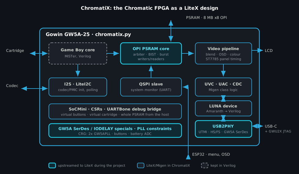
The Chromatic is more interesting than its retro shell suggests. Inside there is a Gowin GW5A-25 (Arora V family), 8 MB of AP Memory APS6408L octal PSRAM, an ST7785 LCD panel on a 6-bit parallel bus, a TI TLV320 audio codec, a PMIC, a cartridge slot wired to the FPGA, and an ESP32 that runs the console menu and on-screen display. The USB-C port goes straight to FPGA pins for USB 2.0, and the same port also carries a Gowin GWU2X JTAG bridge, so the FPGA flash can be written over the charging cable with openFPGALoader.
ModRetro published the FPGA design as oss-chromatic-console-fpga and the ESP32 firmware as oss-chromatic-console-mcu, which is rare and very welcome for a commercial console. The FPGA project wraps the MiSTer Game Boy core with hand-written Verilog, SystemVerilog and VHDL for the board support, and it is built with the Gowin IDE from a TCL project. It needed a specific Gowin release and a license, and several blocks were Gowin IP delivered encrypted or pre-synthesized: the USB 2.0 soft PHY, the USB device controller, a 1K FIFO, the video FIFO, the colour space converter and a fixed-point divider. So the source was open, but you could not read, simulate or port the parts that touch USB, and you could not build it without the vendor toolchain and its license.
We wanted the Chromatic as a LiteX platform. That means a design we can rebuild from Python, port to other cores, simulate and test from scripts, and that reuses (and feeds) the LiteX ecosystem. Rewriting it from scratch would have been the quick way to break a working console. We migrated it instead.
Migrating without breaking it#
The rule was simple: the console keeps working after every step. Each block went through the same
loop, documented in
doc/MIGRATION.md:
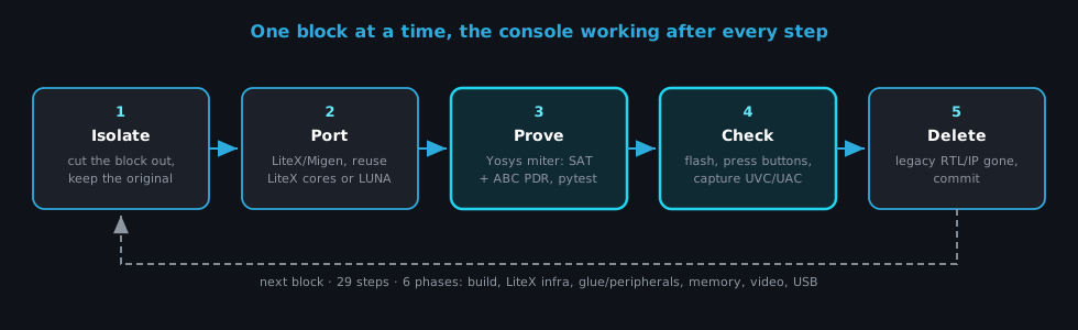
First we isolate the block, splitting it into smaller pieces when needed, and keep the original as the reference. Then we port it to Migen, reusing LiteX cores wherever they exist: the GW5APLL clock generator, RS232PHY for the UART, LiteI2C for the codec and PMIC, stream FIFOs, UARTBone. For the USB device controller we integrated LUNA from Great Scott Gadgets.
The third step is the one that gives confidence: proving the new block equivalent to the old one.
test/eqcheck.py builds a miter with Yosys, a circuit that instantiates the original Verilog
(read straight from the git history) and the new Migen output side by side, feeds them the same
inputs and asserts their outputs are always equal. A bounded check (SAT) proves it for the first N
clock cycles. An unbounded proof with ABC’s PDR engine (property-directed reachability, which
searches for an invariant that holds in every reachable state) proves it for all time. When a block
could not be compared one-to-one, behavioural simulations in pytest covered it instead.
Then the console checks it: build, flash, drive the hardware from the host and look at what comes out (more on this loop in the next section). Only after both checks pass is the legacy RTL deleted and the step committed.
The 29 steps fall into six phases: the build (the TCL project replaced by chromatix.py), the
LiteX infrastructure (SoCMini, CSRs, debug bridge), glue logic and peripherals (clocking, I2C, I2S,
UART, codec and LCD init, system monitor, battery ADC), memory, video and finally USB. The first
fifteen steps, the board support glue, were done in April. The memory, video and USB phases, the
ones with the encrypted IP, came together at the end of September. The repository keeps ModRetro’s
history intact up to their v18.8 release, so the migration is readable commit by commit.
Hands and eyes on the hardware#
A migration with a hardware check after every step only works if the check is cheap. So one of the
first things we added was a debug bridge: with --with-debug-bridge, the USB CDC port becomes a
LiteX UARTBone running directly on the USB stream at High-Speed rate. From the host we get virtual
buttons, status and debug registers, and the whole PSRAM. The console’s USB video output (UVC)
gives us the screen, and the USB audio output (UAC) gives us the sound.
litex_server --uart --uart-port /dev/ttyACM0 &
./scripts/chromatic.py press start --duration 0.2
./scripts/chromatic.py capture frame.png --size 320x288
./scripts/chromatic.py sequence "press:start wait:1.5 press:a wait:1.5 capture:menu.png"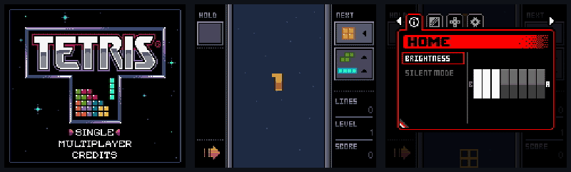
With that, the hardware check is a script: boot a known game, press buttons, capture frames and compare. It is also exactly the interface an AI agent needs. We used agents a lot on this project, and having the console’s buttons and screen behind a command line is what let them build, flash and check a block without anyone holding the console. The engineering decisions stayed ours; the repetitive build/flash/press/capture cycles did not have to be.
USB: from encrypted IP to a LiteX PHY#
USB was the hard part, and the reason the project is worth more than a cleanup.
A USB 2.0 port normally needs a PHY chip: High-Speed USB signals at 480 Mb/s on one differential pair, with Full-Speed (12 Mb/s) signalling, a chirp handshake to negotiate High-Speed, bit stuffing and NRZI encoding on top. The PHY hides all of this behind UTMI, a standard 60 MHz, 8-bit interface that USB device controllers expect. The Chromatic has no PHY chip: the USB-C data lines go directly to FPGA pins, and the original design used Gowin’s encrypted soft PHY, which uses the GW5A’s I/O serializers to do the PHY’s job in fabric.
We replaced it with
USB2PHY, a soft USB 2.0 UTMI PHY written for
LiteX from the USB 2.0 and UTMI specifications. It supports High-Speed, Full-Speed and Low-Speed.
On the receive side there is no recovered clock to lean on, so the High-Speed path samples the line
4x per bit with the GW5A input deserializers and recovers the data in fabric. That tolerates the
±500 ppm frequency offset the spec allows between host and device. The vendor-specific part is
small: the core is written against generic SerDesInput/SerDesOutput/DifferentialTristate
specials, which we added to LiteX in the same series (#2638),
and the GW5A lowering of those specials is about a hundred lines. Another FPGA family needs its own
lowering of the specials, not a new PHY. A Full-Speed-only mode came right after
(#2649), together with a Xilinx lowering of the
differential tristate, so the PHY is not a Gowin-only story.
The encrypted device controller went next, replaced by LUNA’s USB 2.0 device core (Amaranth,
converted to Verilog at build time by LiteX). The USB class logic on top, UVC for video, UAC for
audio and CDC-ACM bridged to the ESP32 UART, was ported to Migen and formally checked against the
originals. The PHY and device controller commits alone deleted more than 18,000 lines. The LiteX
LunaCDCACM core also gained a UTMI mode on the way
(#2640), so any LiteX SoC with this PHY gets a
High-Speed USB serial port.
Once the USB stack was ours, we could improve it. The UVC capture now offers 320x288 as well as the native 160x144: an exact 2x2 upscale where each YUY2 chroma pair maps to one source pixel, so colours are exact. It runs at 60 fps using high-bandwidth isochronous transfers (2048 bytes per micro-frame). The idea came from germaneguise in ModRetro PR #10.
PSRAM: a clean OPI controller#
All the memory traffic in the console goes through one 8 MB APS6408L: the Game Boy frame buffer, the ESP32’s OSD (written over QSPI), the line readers of the video pipeline, and, as we will see, the main RAM of a RISC-V CPU. The chip is an OPI (octal) PSRAM: 8 data lines at double data rate, a data strobe (DQS) for reads, and variable latency.
We first ported the original VHDL controller to Migen as a regular migration step, which kept the
console working while the rest moved. Then we replaced it with a clean controller written
from the AP Memory datasheet: litex/soc/cores/ram/opi_psram.py, BSD-2-Clause, merged in LiteX
with #2649. It does the initialization
sequence, read-path calibration on DQS, linear bursts with byte masks, and splits bursts to respect
the maximum CE# low time. Like the USB PHY, it is written against generic SerDes specials, so it is
not tied to Gowin. On the Chromatic it runs at 67 MHz and passes an 8 MB memtest.
Around it, ChromatiX keeps the console-specific parts: a round-robin arbiter, burst writers for the Game Boy frame buffer and for the ESP32 QSPI slave, and the line readers that feed the video pipeline (frame blending, OSD overlays, Game Boy Color colour correction, ST7785 panel timing).
What went back into LiteX#
| Where | PR | What |
|---|---|---|
| LiteX | #2638 | Generic SerDes and DifferentialTristate specials, GW5A lowering, SerDes/IODELAY helpers |
| LiteX | #2639 | Gowin generated-clock constraints on PLL output pins |
| LiteX | #2640 | LunaCDCACM UTMI mode (High-Speed USB serial) |
| LiteX | #2641 | USB2PHY: soft USB 2.0 UTMI PHY (HS/FS/LS) |
| LiteX | #2649 | USB2PHY Full-Speed mode, SerDesTristate, OPI PSRAM core |
| litex-boards | #812, #820 | modretro_chromatic: cartridge, link, IR, QSPI, I2S, ESP32 UART, HDMI debug pins |
| litex-boards | #862 | High-Speed USB CDC-ACM console with USB2PHY |
| litex-boards | #863, #865 | SoC reset, PSRAM as main RAM |
These came on top of a series of Gowin backend improvements merged in September (PLL limits per
device density, generated clocks, false paths, GWU2X cable presets in GowinProgrammer), which the
Chromatic target relies on. None of this is Chromatic-specific: a soft USB 2.0 PHY and an OPI PSRAM
controller are useful to anyone putting LiteX on a small FPGA with no PHY chip and a PSRAM next to
it, which is a very common board design. ChromatiX now depends on LiteX master for them.
The litex-boards target is the minimal version: python3 -m litex_boards.targets.modretro_chromatic --with-usb-acm --with-psram --with-lcd-terminal --build gives a VexRiscv SoC with a High-Speed USB
serial console, PSRAM main RAM and a terminal on the LCD, with no Game Boy involved. ChromatiX is the full console on top of the same pieces.
What it opens up#
Once the design is LiteX, the Chromatic stops being a closed appliance. A few things we built on top of it in the following days:
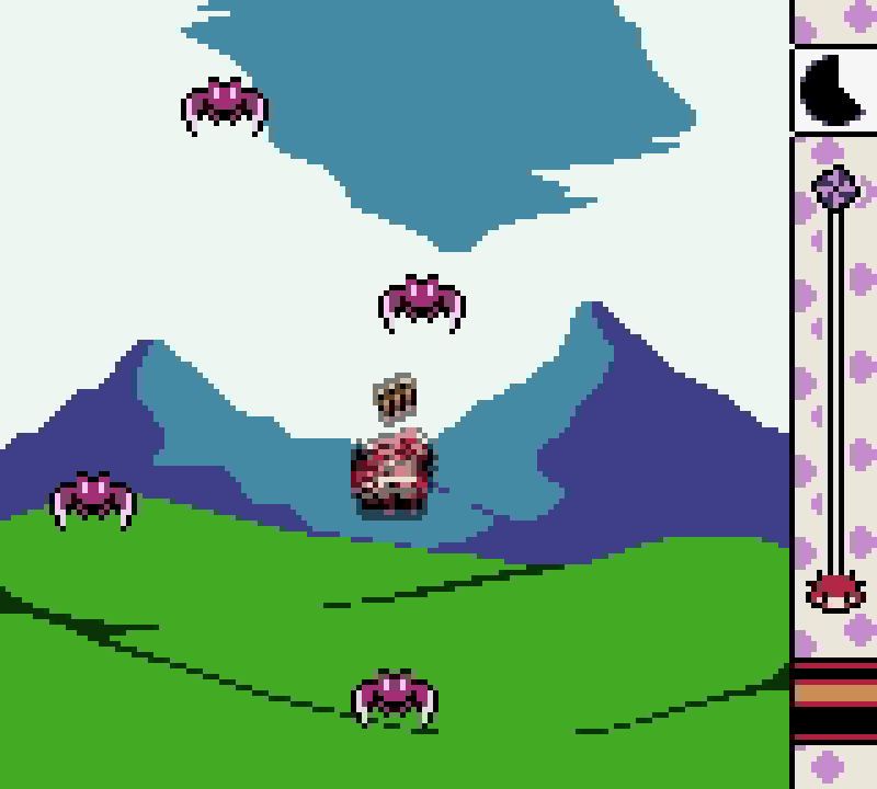
A virtual cartridge. With the debug bridge, Game Boy and Game Boy Color ROMs up to 3.5 MB load from the PC into the PSRAM (about 0.1 s per 256 KB) and run without a cartridge. MBC1, MBC2, MBC3 and MBC5 mappers are supported, cartridge RAM lives in PSRAM too and can be saved back to the PC. A 4 KB cache sits on the highest-priority PSRAM port, and the Game Boy core is frozen for a few cycles on a miss; on hardware that happens about 0.04% of the time, which no game notices.
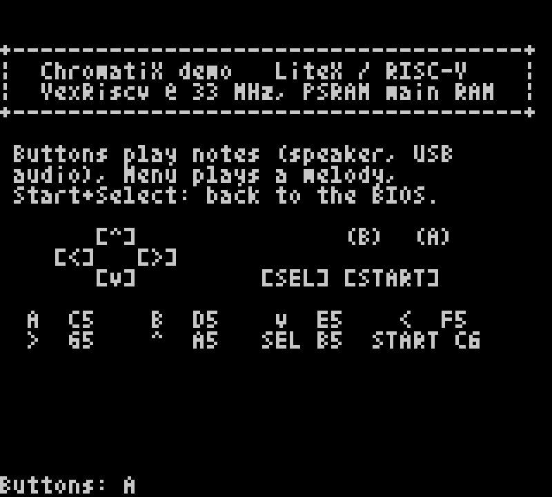
A LiteX development board. --with-bios replaces the Game Boy core with a VexRiscv SoC at
33 MHz running the LiteX BIOS. The console shows up on the USB serial port and on the LCD as a
40x24 text terminal (and so over UVC), the upper 4 MB of PSRAM are main RAM behind an L2 cache, and
firmware loads over serialboot. A small demo maps the buttons to notes on a tone generator.
A simulation. chromatix_sim.py runs the whole Game Boy core in Verilator (the VHDL parts
converted with GHDL), with a cartridge model or the virtual cartridge on a PSRAM model, the video
pipeline, an SDL window with keyboard or gamepad, and save files. It is cycle accurate and runs
around 2 fps on a desktop CPU, which is slow motion but enough to debug the video path without the
console.
Compatibility with community firmware. On a separate branch, the design is being made compatible with ChroMagic, a GPL custom ESP32 firmware that plays games from the SD card through the stock menu: the virtual cartridge follows ChroMagic’s PSRAM map, and the QSPI and system-monitor links follow its protocol, so its firmware runs unchanged.
The CPU mode is where it gets fun. A CPU with 7.5 MB of RAM, a 160x144 screen, buttons, audio and a fast USB link is enough to run Doom, and the ESP32 sitting next to the FPGA has a 2.4 GHz radio that can be turned into an SDR. Both are their own posts: Doom on ChromatiX and ChromatiX SDR.
Licensing, releases and limits#
ChromatiX is licensed per file. The ports of ModRetro’s design stay GPL-3.0, like the original, and our new work (the LiteX adaptation, new modules, tools, tests) is BSD-2-Clause. The MiSTer core is GPL, so built bitstreams are GPL. No Gowin-derived code is left in the repository.
There are three bitstreams: chromatix-standard.fs (a drop-in replacement of the official design),
chromatix-vcart.fs (standard plus debug bridge and virtual cartridge) and chromatix-bios.fs (the
LiteX BIOS demo). scripts/chromatix_flash.py writes them over the GWU2X bridge, and it backs up
the official flash image before the first write. We checked that restoring that backup gives a flash
image bit-identical to the official dump. JTAG stays available whatever is in the flash, so an
interrupted write can simply be retried.
The limits are honest ones. The build still needs the Gowin toolchain, V1.9.12.04 specifically:
V1.9.10 builds do not enumerate on USB and V1.9.9 fails timing. The open Gowin flow
(Apicula/nextpnr) does not support the GW5A-25 yet, and LiteX rejects that combination explicitly.
USB only enumerates when the FPGA boots from flash, not from a JTAG load. The design uses around
three quarters of the GW5A-25’s logic. And CI is paused for a GitHub Actions billing reason, not a
technical one; the test suite (formal checks included) runs locally with pytest.
Try it#
From prebuilt bitstreams, with only openFPGALoader installed (see the releases):
./chromatix_flash.py info                          # Console on, USB-C connected.
./chromatix_flash.py flash chromatix-standard.fs   # Backs up the official image first.
./chromatix_flash.py restore                       # Back to the official image.
From source, with LiteX master and Gowin V1.9.12.04:
git clone --recursive https://github.com/enjoy-digital/chromatix
cd chromatix && pip3 install --user -e .
./chromatix.py --gowin-path ~/tools/gowin_1.9.12.04/IDE --build --flash
./chromatix.py --gowin-path ~/tools/gowin_1.9.12.04/IDE --with-debug-bridge --build --flash
./scripts/chromatic.py load-rom game.gb
python3 -m pytest -n auto test
The promo video at the top of the README is rendered with three.js from the repository too.
Built on LiteX, LiteX-Boards, LUNA and Amaranth, with Yosys, Verilator and openFPGALoader. Thanks to ModRetro for opening the Chromatic’s FPGA and MCU designs, to the MiSTer Game Boy core contributors, and to germaneguise for the 320x288 capture idea. ChromatiX is not affiliated with or endorsed by ModRetro; ModRetro and Chromatic are trademarks of ModRetro.
Work and ideas by Enjoy-Digital; written up with AI in the loop.