TL;DR: ESP-SDR, from ESPARGOS, uses an
undocumented debug path in Espressif’s radios to capture raw I/Q samples from the ESP32’s
2.4 GHz receiver. The ModRetro Chromatic has an original ESP32 wired to its FPGA, and since
ChromatiX the FPGA is a LiteX design we can extend. On the
sdr branch, the ESP32 runs ESP-SDR with a
small Chromatic patch, the captures travel over the console’s existing QSPI link straight into
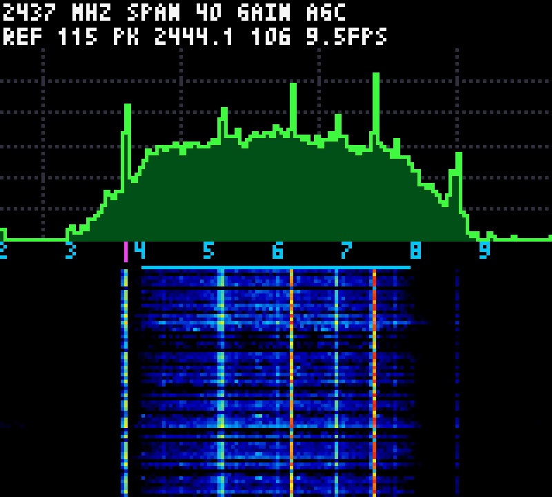
PSRAM, and a VexRiscv computes the FFT and draws a spectrum, waterfall and band scan on the LCD
at about 26 updates per second. We also pushed the tuning from the Wi-Fi channel frequencies to
1775-2890 MHz, partly thanks to a finding from the community. On top of the spectrum views,
the console now decodes: an LTE cell scanner that finds carriers and decodes the cells’ MIB, a
BLE advertising scanner, a 2.4 GHz signal classifier, and DECT and 802.15.4 sniffers, all on the
67 MHz softcore. Over USB, the console relays the captures to the PC at 2.4 MB/s, and a SoapySDR
module makes it a source for gqrx, CubicSDR and GNU Radio. It is a burst receiver with a 2.4 GHz
antenna, not a wideband SDR, and the post is clear about that too.
ESP-SDR in two minutes#
An ESP32’s radio is built for Wi-Fi and Bluetooth. Between the RF front-end (LNA, mixer, filters) and the CPU sits a fixed-function modem that turns the received signal into packets, and normally software only ever sees the packets. ESP-SDR, published by ESPARGOS (Florian Euchner) at the end of September 2026, uses an undocumented debug path that bypasses the modem and hands the ADC output, I/Q samples, to the CPU. The firmware captures short bursts into internal memory and sends them over UART or USB. It supports most of the ESP32 family, and its README is open about how it was done: the path was found and generalised across chips with the help of LLMs.
On the original ESP32, which is the one in the Chromatic, ESP-SDR offers 16, 40 or 80 MS/s, 8 or 10-bit samples, manual gain from 0 to 72 or the hardware AGC, and bursts of up to 16380 samples. A 4096-sample capture at 40 MS/s covers 104 µs. That is the important limitation: these are snapshots, not a continuous stream, so the receiver sees a few percent of the time at best. For a spectrum display, a waterfall or hunting bursts, that is fine. For demodulating a continuous signal, it is not.
What the console adds#
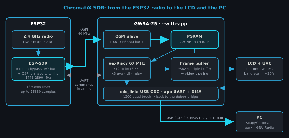
The Chromatic’s ESP32 normally runs ModRetro’s menu and OSD firmware. Around it, the console provides everything a handheld SDR needs and the bare chip does not have: a screen, buttons, a speaker, a battery, a fast USB 2.0 port, and an FPGA connected to the ESP32 by a UART and a quad SPI link.
The FPGA side reuses the application SoC we built for Doom: a VexRiscv
with 8 KB caches at 67 MHz, 7.5 MB of PSRAM as main RAM behind an L2, a tear-free PSRAM frame
buffer, PCM audio and the buttons. --with-app builds it, with one addition: a CPU UART wired to
the ESP32’s UART0. That build uses 69% of the logic and 48 of the 56 BSRAM, and meets timing at
67 MHz.
Moving the samples#
The first test used stock ESP-SDR and the standard ChromatiX bitstream, which bridges the USB serial port to the ESP32’s UART at 2 Mbaud. It worked, at about 31 KB/s, and roughly one capture in twelve failed its CRC: the bridge’s 64-byte FIFO overflowed whenever the host did not poll fast enough. Good enough to check the receiver works through the console’s antenna, not good enough for anything else.
The second step put the CPU on the ESP32’s UART directly, with a 512-byte receive FIFO. That gave 122 KB/s and 50 clean captures out of 50, but a 4096-sample capture still took 67 ms, 41 of them for the transfer. Stock ESP-SDR cannot go faster than 2 Mbaud on this UART.
The third step used a link that was already there. The ESP32 draws the console’s on-screen menu by
writing into the FPGA’s PSRAM over quad SPI at 40 MHz, and ChromatiX has a QSPI slave that turns
each 1 KB transfer into a PSRAM burst. Our ESP-SDR patch adds a QSPI <address> command: after
it, capture payloads go over QSPI to that PSRAM address and only the DATA header (length, CRC32,
duration) stays on the UART. No gateware change was needed. The CPU invalidates its caches, reads
the payload from its main RAM and checks the CRC. A full 16380-sample capture round trip went from
about 170 ms over the UART to 7.3 ms.
DSP on a 67 MHz softcore#
The console computes the spectrum on the VexRiscv, in C. Each 4096-sample capture is split into 8 segments; each segment gets its DC offset removed and a Hann window, goes through a 512-point radix-2 FFT, and the 8 power spectra are averaged and converted to a log scale in quarter-dB steps. The first FFT used 32-bit arithmetic. The current one uses 16-bit samples with block scaling (the whole block is shifted down only when a stage could overflow), which is enough precision for a display and much faster on an rv32im without DSP instructions. Twiddle factors come from a table generated by a Python script. We checked the result against numpy on the same captures: same peak bins, and a correlation of 0.9999 on the dB shape.
An update takes about 37 ms, 21 of them in the DSP, so the display runs at about 26 updates per second over QSPI, against 9.5 with the UART version.
Tuning beyond the Wi-Fi channels#
Checking the spectrum against known signals showed two problems. The first was simple: the ESP32’s spectrum is inverted, so every client conjugates the I/Q samples. The reference was the console’s own 24 MHz crystal, whose harmonics at 2400, 2424, 2448, 2472 and 2496 MHz show up as narrow lines at every tuning, which makes them a convenient frequency ruler.
The second was bigger. ESP-SDR accepts any frequency from 100 to 6000 MHz, but on the original ESP32 only the Wi-Fi channel frequencies actually moved the local oscillator: 2412 to 2472 MHz in 5 MHz steps, plus 2484. For other frequencies the firmware calibrates the PLL on 2412 MHz and then writes a new divider, but the VCO’s capacitor bank stays calibrated for 2412 MHz and the LO does not follow. ESP-SDR documents its extended range as not RF-validated, so this is not a bug report; it just meant the receiver could only look at the Wi-Fi channels.
We extended it in three steps. The first two are ours, in chromatic_tune.c, one of the files our
build adds to ESP-SDR; the third came from the community.
The first step uses a function of Espressif’s PHY library, set_chan_freq_sw_start, which we found
by disassembling libphy.a. Wi-Fi and the Bluetooth PHY use it for their channels: it runs the full
calibration on a given MHz (2400 to 2484) plus a fractional offset. The offset turned out to move
the LO by 1.0546 times its nominal value, a factor we measured from the crystal harmonics and
applied. That gave 2386 to 2504 MHz in 1 kHz steps, with the LO within ±2.6 kHz of the request,
which is the crystal tolerance between the console and the ESP32.
The second step went further. The PHY calibration reads its targets from an 85-entry PLL table, one entry per MHz from 2400 to 2484, where each entry holds the VCO capacitor code, the divider (the LO is 480 MHz × (2 + word/2^20), so any frequency above 960 MHz can be encoded) and a front-end tuning word. Loading one entry with the divider for the target frequency and a capacitor code close to the expected result, fitted from the calibration results, makes the calibration lock from 2150 to 2880 MHz, repeatably, with the LO within 2 kHz. To find the real edges, we then forced the VCO capacitor code by hand at each frequency and watched where the PLL locks: a window of 3 to 5 codes that slides from code 255 at 2130 MHz to code 0 at 2890 MHz. Past those, the capacitor bank simply has no more codes. With a better starting code, the calibration reaches both edges, and the table tuning now covers 2130 to 2890 MHz.
The third step came from outside. h0m3us3r’s eSpDR, another ESP32 SDR project, found a selector in the radio’s clock generator (analog block 0x65, register 0, bit 4) that makes the receive LO 5/6 of the PLL frequency. ESPARGOS then qualified it on the original ESP32 in ESP-SDR with a signal generator. Since our table tuning already places the PLL anywhere from 2130 to 2890 MHz, combining the two was direct: below 2150 MHz, the firmware tunes the PLL to 6/5 of the requested frequency (calibrating in the normal mode), then sets the selector once the receive path is configured. With the PLL starting at 2130 MHz, that extends the range down to 1775 MHz, with the LO within 1 to 4 kHz of the request across the 5/6 range. The console now tunes 1775 to 2890 MHz in 1 kHz steps.
On top of that, opening the receiver’s low-pass filter at 80 MS/s gives a usable view of about ±38 MHz around the LO. The console and the PC can see roughly 1737 to 2928 MHz.
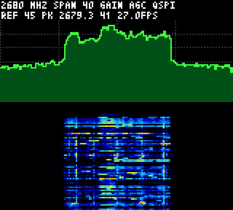
With the antenna and LNA matched for 2.4 GHz, sensitivity outside the ISM band is lower. Real signals still come through: a 15 MHz LTE band 3 downlink carrier at 1845-1860 MHz, the mobile band 1 downlink carriers up to 2170 MHz, and a 20 MHz LTE band 7 downlink carrier at 2680 MHz, each seen at several LO settings so they are not images.
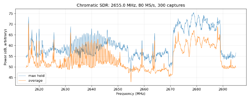
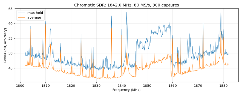
We also looked for more and found nothing, which is worth writing down. Flipping every bit of the clock generator block and measuring the LO ratio each time shows that 5/6 is the only other divider: the remaining bits either stop the receive path or do nothing. We mapped the other analog blocks the same way without finding a frequency doubler, and with 5 GHz access points nearby, no LO harmonic picked up anything at 5.2 or 5.5 GHz. The original ESP32 is a 2.4 GHz-only chip, front-end included. The ESP32 SDR projects that reach 5.8 GHz, like ESPsoup and C5VRX, run on the dual-band ESP32-C5; on the Chromatic, that would mean an ESP32-C5 on a cartridge PCB streaming to the FPGA, or a downconverter in front of the antenna.
Our ESP32 firmware is ESP-SDR pinned to a specific upstream commit, plus a small patch and three
source files (the QSPI transport, the tuning and a capture delay we come back to below), all applied by firmware/esp32-sdr/build.sh. The
protocol is unchanged, so the same firmware still works as a stock ESP-SDR with ESPARGOS’ viewers. We plan to propose the table tuning to ESP-SDR upstream, since
every original-ESP32 user would benefit from it, not only the Chromatic. The 5/6 mode shows how
well this works in the other direction: found in eSpDR, qualified in ESP-SDR, and in our firmware
the next working day.
The handheld UI#
The firmware on the console became a small instrument. The header shows the frequency, span, tuning step and the level at the peak or at the cursor. Under it, a spectrum with a frequency axis, known bands, Wi-Fi channel numbers, the three BLE advertising channels and an optional peak hold, then a waterfall.
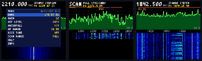
Select switches between three views: spectrum with waterfall, waterfall only, and a band scan that sweeps a range in 64 MHz steps with wide 80 MS/s captures, from the 2.4 GHz ISM band to the full 1775-2890 MHz range in 18 steps. Left and Right tune (faster when held), Up and Down change the tuning step from 10 kHz to 20 MHz, A changes the span between 16, 40 and 80 MHz, B brings up a cursor that A tunes to. The menu has band presets (Wi-Fi channels 1, 6 and 11, Bluetooth, DECT, and the LTE bands in range, from band 3 at 1.8 GHz to band 7 at 2.6 GHz), gain, reference level, waterfall settings and help pages.
The RSSI tone is our favourite feature. It plays a tone through the speaker, with the pitch following the level at the cursor, so you can tune to an emitter and walk around the room to find it without looking at the screen.
From spectrum to decoding#
A spectrum shows that something is there; the next question is what. So the menu gained a TOOL
entry that replaces the spectrum views with a dedicated tool, each with its own help page. They
share the radio, display and button services of the application, and their DSP is plain C with no
hardware dependency: test/test_sdr_dsp.py builds it on the PC and checks it against synthetic
ESP32 captures, with the same 8-bit samples, inverted spectrum, noise and frequency offsets as the
real receiver. Each decoder was right on synthetic data before it ever ran on the console.
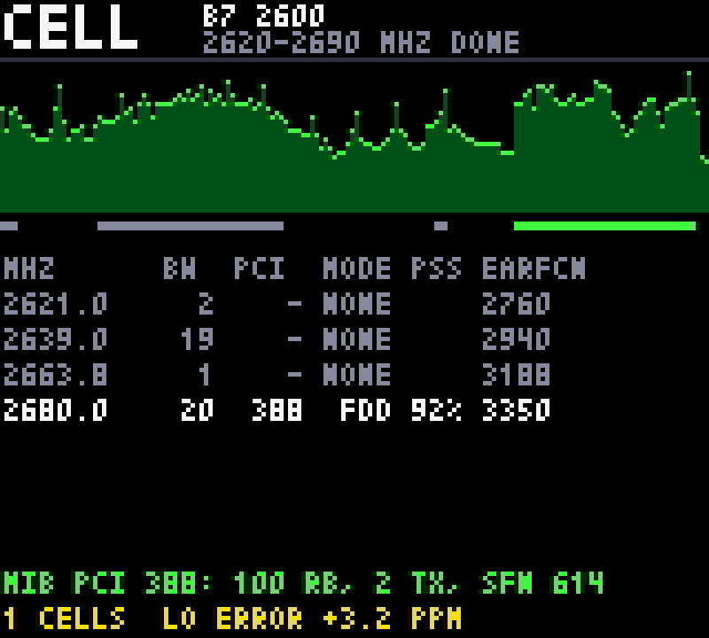
The cell scanner is the most involved. It sweeps an LTE band with wide 80 MS/s captures and finds the carriers: bins above the noise floor are clustered and matched against the LTE bandwidths (a lightly loaded carrier is not flat, only its reference signals fill the unused resource blocks, so the clustering has to bridge gaps). For each carrier it then takes 1 ms captures at 16 MS/s, channelizes them down to the 1.92 MS/s of the LTE synchronization signals and looks for a cell. The primary sync signal (PSS) is found by FFT correlation and gives the timing and a first frequency offset; the secondary one (SSS) gives the physical cell ID (PCI) and whether the cell is FDD or TDD. Then comes the MIB, the small block every LTE cell broadcasts on its physical broadcast channel (PBCH) with its bandwidth and frame number: channel estimation from the cell’s reference signals for one or two antenna ports, Alamouti transmit diversity, descrambling, rate dematching, a tail-biting Viterbi decoder and the CRC, whose mask also gives the number of transmit antennas. On band 7 here, it decodes PCI 388, FDD, 100 resource blocks (20 MHz), two transmit antennas and a consistent frame number, and it measures the console ESP32’s own crystal error at about +3 ppm as a side effect. A capture takes about 210 ms of processing on the VexRiscv.
The MIB took a fix on the ESP32 side. The PSS is sent every 5 ms and the PBCH follows 0.35 ms after
it in one out of two, so a 1 ms capture needs the right phase. ESP-SDR handles commands on the
1 ms FreeRTOS tick, so every capture started on the same 1 ms grid of the ESP32’s clock: against
the LTE frame, the PSS was always about 0.8 ms in and the PBCH never fit. Our firmware adds a
CAPDLY command, a random delay of up to 1 ms before each capture, and the captures now land
everywhere in the frame: 16 MIBs out of 47 cell detections on real band 7 captures.
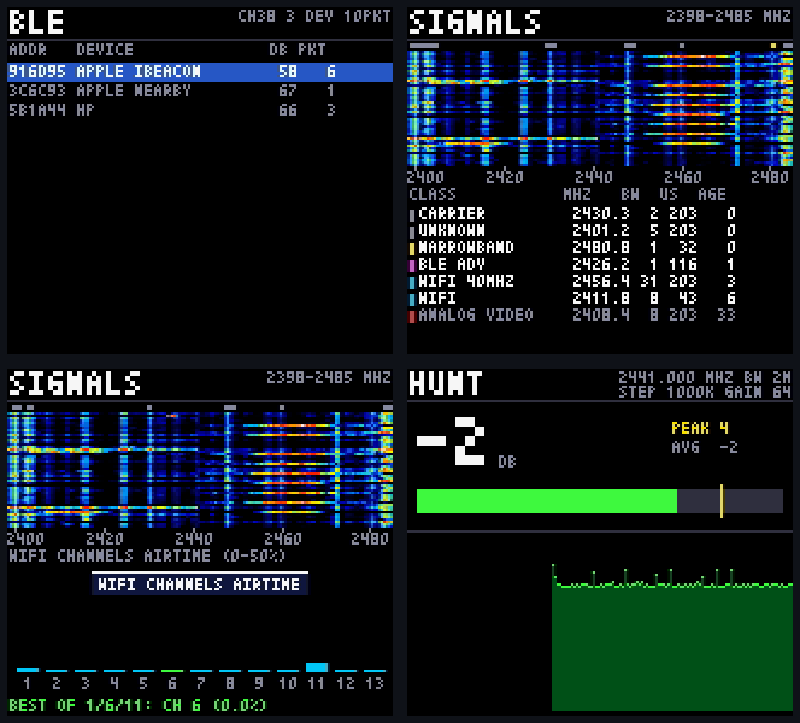
The other tools, briefly:
- BLE scanner. Hops over the three advertising channels with 1 ms captures (a whole advertising packet fits), demodulates the GFSK with an FM discriminator, searches the access address and checks the CRC. It lists devices with names, vendors and Apple Continuity types, flags trackers (Find My, SmartTag, Tile, Chipolo) and has a find mode that beeps on each packet of the selected device. A capture covers about 1% of the air time, so devices show up over tens of seconds rather than instantly.
- Signal identification. Captures the whole 2.4 GHz band in two 80 MS/s halves, builds a spectrogram with 1.6 µs time cells, and classifies the bursts by bandwidth, duration and channel: Wi-Fi 20/40 MHz, BLE advertising, 802.15.4, narrowband links, carriers, and the signatures of drone video links, DJI DroneID, analog video and microwave ovens. A drone alert requires long bursts seen twice in 10 s. The Wi-Fi classes are checked on the air; the drone classes are heuristics we have not been able to test against a real drone. A second view shows the airtime per Wi-Fi channel and the least busy of 1, 6 and 11.
- DECT scanner and 802.15.4 sniffer. Decode DECT base station identities from their beacons (control part only, no voice), and 802.15.4 frames up to the MAC header (PAN IDs, Zigbee/6LoWPAN, addresses). There is no DECT base or Zigbee network in our lab, so these two are verified on synthetic captures only.
- Hunt. Channel power in a 100 kHz to 10 MHz bandwidth anywhere in the tuning range, with an auto-ranged gain correction, peak hold, history and the RSSI tone: the tool for finding an interferer or pointing the console at a transmitter.
Getting this to run on a 67 MHz rv32im with an 8 KB direct-mapped data cache took some care. Real
and imaginary parts in separate arrays a multiple of 8 KB apart evicted each other on every access,
ten times slower; the DSP now uses interleaved complex samples and offsets the buffers it uses
together. Compiling the DSP with -O3 -funroll-loops instead of -Os took the BLE decode from
192 ms to 71 ms, because the unrolled loops hide the load and multiply latencies. And nothing uses
64-bit products: the FFT builds its 32x16-bit products from 32-bit multiplies.
On the PC#
To use the console as a regular SDR, the USB serial link had to carry more than the debug bridge.
A small gateware block, cdc_link, lets the application switch the USB CDC byte stream from the
UARTBone debug bridge to its own UART for commands and a DMA reader for bulk data from main RAM.
Opening the port at 1200 baud, the same “touch” Arduino boards use, switches it back to the debug
bridge so the host tools keep working.
The console then acts as a relay. It forwards ESP-SDR commands from the PC to the ESP32, answers the transport commands itself, and after each capture header sends the payload, already in PSRAM from the QSPI transfer, by DMA. It still displays the relayed captures, and resumes its own captures two seconds after the PC goes quiet.
On the PC, scripts/chromatic_sdr.py covers quick checks (info, benchmark, spectrum, recording to
a CS8 file). software/SoapyChromatic is a SoapySDR module that speaks the same protocol, so gqrx,
CubicSDR, GNU Radio and SoapySDR’s Python bindings see the Chromatic as a normal device: 16, 40 or
80 MS/s, AGC or a gain element, kHz tuning through FREQK with an NCO for the sub-kHz rest, and
burst timestamps. ESPARGOS’ own SoapySDR module targets the ESP32-S31 over Ethernet, so this one
fills the original ESP32’s spot.
The relay sustains 73 captures of 16380 samples per second, 2.4 MB/s or about 1.2 MS/s of delivered samples, with no errors over 833 captures (27 MB) in the benchmark. Through SoapySDR, Python gets 1.0 MS/s and a GNU Radio source 1.12 MS/s. One 512-byte USB packet was lost once in about 13,000 relayed captures; the clients detect it with the CRC and drop the capture, and the root cause is still open.
Limits#
We want to be clear about what this is. It is a 2.4 GHz-centred receiver that sees roughly 1.74 to 2.93 GHz in bursts of 0.2 to 1 ms, with a duty cycle of a few percent. It is good for watching Wi-Fi and Bluetooth activity, finding emitters, looking at band occupancy, and identifying LTE cells, BLE devices and 2.4 GHz signals in range. There is no broadcast FM, no ADS-B at 1090 MHz and no GPS at 1575 MHz: they are below even the 5/6 LO range, and we checked that no second-order or harmonic trick reaches them usefully. The console’s own 24 MHz harmonics show up as spurs.
The tools share the same limit: they sample the air rather than watch it. Captures are 1 ms long at 16 MS/s and a few per second, long 802.15.4 frames and full DECT frames do not fit in one, and only the unencrypted headers are decoded (LTE synchronization and MIB, BLE advertising, the DECT control part, the 802.15.4 MAC header). UMTS carriers are found but not decoded.
Flashing ESP-SDR also replaces ModRetro’s ESP32 firmware, so while it is installed the console has no menu, OSD, settings or power management. Back up the ESP32 flash first (the command is below) and restore it to get the console back. Merging the SDR transport into the ModRetro MCU firmware, so the SDR becomes a mode rather than a replacement, is on the list.
Try it#
The ESP32 firmware is built from ESP-SDR plus our patch, with the ESP-IDF version ESP-SDR pins, and flashed through the ChromatiX USB-to-ESP32 bridge of the standard bitstream:
git clone --recursive -b sdr https://github.com/enjoy-digital/chromatix
cd chromatix

# Back up the ModRetro ESP32 firmware first (restore: write_flash 0 esp32_backup.bin).
esptool.py --port /dev/ttyACM0 --chip esp32 --baud 460800 read_flash 0 0x400000 esp32_backup.bin

# ESP-SDR + Chromatic patch (ESP-IDF sourced), then flash it through the bridge.
./firmware/esp32-sdr/build.sh
(cd firmware/esp32-sdr/build/esp-sdr/build-esp32 && \
    python -m esptool --chip esp32 -p /dev/ttyACM0 -b 460800 write-flash @flash_args)

# Application SoC, SDR firmware.
./chromatix.py --gowin-path ~/tools/gowin_1.9.12.04/IDE --with-app --build --flash
make -C firmware/sdr BUILD_DIR=../../build
./scripts/chromatic.py --serial /dev/ttyACM0 run firmware/sdr/sdr.bin --no-verify
Then, on the PC, with SoapyChromatic installed from software/SoapyChromatic, gqrx opens it with
the device string soapy=0,driver=chromatic. All the measurements, checks and dead ends are in
doc/SDR.md.
The foundation of all this is ESP-SDR by ESPARGOS (Florian Euchner, esp-sdr, GPL-3.0): the raw I/Q capture of the ESP32 radio, its firmware and protocol. The 5/6 LO mode comes from h0m3us3r’s eSpDR. ChromatiX adds the Chromatic transport and tuning patch, the console application and the PC side. Thanks to ModRetro for the open MCU and FPGA designs that made the QSPI link easy to reuse. Built on LiteX and SoapySDR.
Work and ideas by Enjoy-Digital; written up with AI in the loop.