TL;DR: the Adiuvo Forgix puts an RP2350 and an Efinix Trion T8 on one small board. MicroPython on
the RP2350 loads the FPGA bitstream over SPI (streamed straight from the host via mpremote mount,
nothing stored in flash), then reuses the same three pins as a SPIBone bridge into a CPU-less LiteX
SoC: read the identifier, round-trip the scratch register, drive the RGB LED. Python owns the bus;
the FPGA does not need a CPU at all.
No softcore this time#
A few weeks ago I wrote about MicroPython on LiteX: describe the SoC in Python, then run Python on the softcore inside it. This note is the same joke told backwards. The Python still runs right next to the FPGA fabric, but this time on a hard CPU that was already sitting there, and the LiteX SoC in the fabric has no CPU at all.
More and more boards ship an MCU and an FPGA side by side, and when a perfectly good Cortex-M (or here, a dual-core RP2350) is soldered a centimeter away from the fabric, spending LUTs on a softcore just to poke registers feels like bad economics. What you actually need is a way for the MCU to reach the SoC bus. That is exactly what SPIBone does: a small bridge that turns a few SPI pins into a Wishbone master.
Regular readers will recognize the shape. ColorLite was a CPU-less SoCMini
whose entire bus was exposed over Etherbone/UDP. Same idea here, except the bridge is three wires
of SPI instead of an Ethernet cable, and the master is a $1 microcontroller instead of a host PC.
The aduivo_forgix_test repo documents the
whole flow end to end, following the approach we first used on a
RP2040 PMOD.
The board#
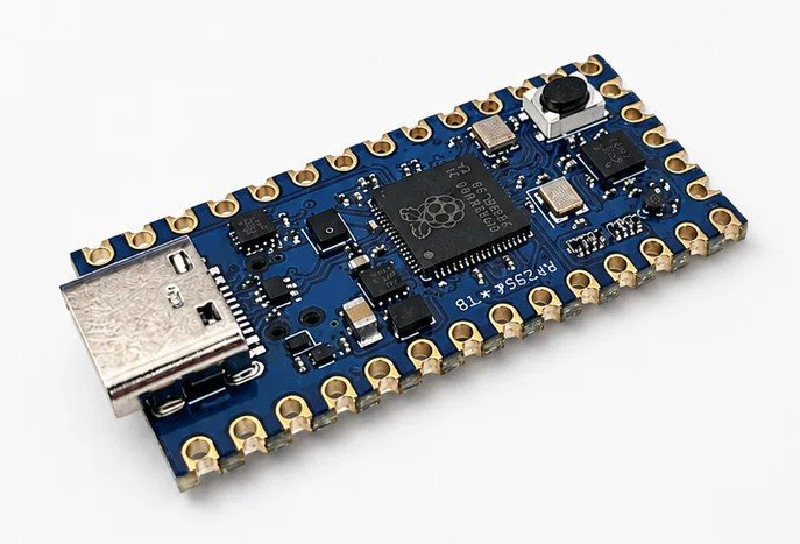
The Forgix is made by Adiuvo Engineering, Adam Taylor’s company, and it is a nicely open one:
the schematic and KiCad files
are public. On it, an RP2350 sits next to an Efinix Trion T8 (T8F49C2), with the RP2350 wired
to the FPGA’s passive-SPI configuration pins. LiteX-Boards has an
adiuvo_forgix target for it.
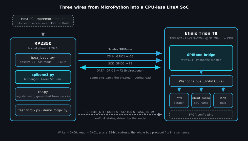
The pins that matter for this note are few. Three for the shared SPI:
| Signal | RP2350 GPIO | FPGA pin |
|---|---|---|
| CS_N | 1 | G3 |
| SCK | 2 | F3 |
| MOSI / bidirectional data | 3 | F2 |
And four more that the loader uses to control configuration:
| Signal | RP2350 GPIO |
|---|---|
| FPGA RESET / CRESET_N | 4 |
| FPGA DONE | 5 |
| FPGA STATUS | 6 |
| FPGA OSC_EN | 19 |
The same three SPI pins do double duty: passive-SPI bitstream loading first, SPIBone bus access after. No MISO pin is claimed anywhere: three wires is really all it takes.
Three wires into the bus#
The SPIBone core has been in LiteX for a while (originally written by Sean Cross in 2019), and it
comes in 4-, 3- and 2-wire flavors. The adiuvo_forgix target instantiates the 3-wire one and
simply adds it as a bus master:
# litex_boards/targets/adiuvo_forgix.py
if with_spibone:
    self.spibone = SPIBone(platform.request("spibone"), wires=3)
    self.bus.add_master(name="spibone", master=self.spibone.bus)
That is the entire trick. The SoC is a SoCMini with an identifier, a control block and the RGB
LED, and nothing that executes instructions. The generated register map states it with a straight
face:
# micropython/csr.py, generated from the LiteX build.
CSR_CTRL_SCRATCH       = 0x00000004
CSR_LEDS_OUT           = 0x00001000
CONFIG_CPU_TYPE_NONE   = 'None'
CONFIG_CPU_HUMAN_NAME  = 'Unknown'
The protocol on the wire is as small as the SoC: a write is 0x00 plus a 32-bit address plus a
32-bit value; a read is 0x01 plus an address, then the master releases the data line and waits
for the command byte to be echoed back before clocking in 32 bits. The whole bus protocol fits in a
sentence. 🙂
Building the gateware#
The build is one LiteX-Boards command, with Efinity doing the place-and-route behind the scenes (this flow was validated with Efinity 2025.1):
python3 -m litex_boards.targets.adiuvo_forgix \
    --build \
    --with-spibone \
    --output-dir build/adiuvo_forgix
Efinity emits the passive-x1 image as gateware/outflow/adiuvo_forgix.hex. Two small host tools
prepare the RP2350 side: one converts that text .hex into a raw .bin for the fast loader path,
the other regenerates the MicroPython register map from the LiteX csr.csv:
python3 tools/bitstream2bin.py \
    build/adiuvo_forgix/gateware/outflow/adiuvo_forgix.hex \
    --output build/adiuvo_forgix/gateware/outflow/adiuvo_forgix.bin
python3 tools/csr2py.py build/adiuvo_forgix/csr.csv --output micropython/csr.py
So csr.py is not hand-written: it is the same self-describing-SoC story as everywhere else in
LiteX, just rendered down to a flat file of constants that fits comfortably on a microcontroller.
Loading the FPGA from MicroPython#
My favorite detail of the flow is what does not happen: the bitstream is never copied to the
RP2350. mpremote mount exposes the host build directory to MicroPython as /remote, and the
loader streams the file from there, over USB, straight into the FPGA. Rebuild the gateware, rerun
the command, and the new design is live, with no flashing step and nothing to clean up.
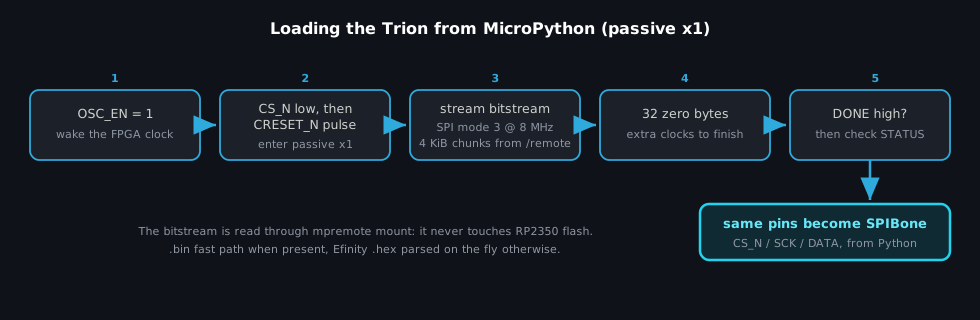
The sequence in fpga_loader.py follows the Trion passive-x1 dance: raise OSC_EN first (the
FPGA’s oscillator is gated), pull CS_N low before releasing CRESET_N so the Trion samples
passive-SPI mode, then stream the image with hardware SPI (mode 3, 8 MHz, 4 KiB chunks), finish
with 32 zero bytes of extra clocks, and wait for DONE with a check on STATUS. On real hardware
the full load-and-test round trip prints its timing, and aborts loudly if DONE or STATUS
disagree.
If the .bin is absent, the loader falls back to parsing Efinity’s .hex output directly: a
small streaming Intel HEX decoder, checksums included, running in MicroPython on the RP2350. We
added the .bin path purely because blasting raw bytes is faster than parsing text on a
microcontroller; the .hex fallback keeps the flow working straight out of the Efinity build,
with no conversion step required.
Poking CSRs from the REPL#
After configuration, spibone3.py takes over the same pins and bit-bangs the 3-wire protocol with
machine.Pin: drive the data pin to send, flip it to an input with a pull-up to receive. The read
path shows the whole protocol in a dozen lines:
# micropython/spibone3.py
def read(self, address):
    self._select()
    try:
        self._write_byte(0x01)
        self._write_u32(address)
        self._release_data()
        self._wait_response(0x01)
        return self._read_u32()
    finally:
        self._deselect()
And using it from the REPL feels exactly like litex_server on a host PC, just smaller:
import csr
from spibone3 import SPIBone3Wire, read_identifier

bus = SPIBone3Wire()
print(read_identifier(bus, csr.CSR_BASE_IDENTIFIER_MEM))
# LiteX SoC on Adiuvo Forgix ...

bus.write(csr.CSR_CTRL_SCRATCH, 0x12345678)
hex(bus.read(csr.CSR_CTRL_SCRATCH))   # '0x12345678'

bus.write(csr.CSR_LEDS_OUT, 0x4)      # RGB LED: blue
That continuity is the point. LiteX users already bring up and debug SoCs from Python scripts over a host bridge, whether Etherbone, PCIe or UART. This is the same mental model with the host shrunk down to the MCU that ships on the board.
Load, test, blink#
The repo bundles it all into one command: mount the build directory, load the FPGA, run the tests:
mpremote connect /dev/ttyACM0 mount build/adiuvo_forgix/gateware/outflow exec \
    "import sys; sys.path.append('/'); import load_and_test; load_and_test.main()"
Forgix LiteX load-and-test
Loading FPGA from /remote/adiuvo_forgix.bin:
wrote 65536 bytes
wrote 131072 bytes
...
DONE=1 STATUS=1
Programmed <bitstream-size> bytes in <elapsed-ms> ms
Forgix LiteX SPIBone test
Identifier:
LiteX SoC on Adiuvo Forgix ...
Scratch CSR:
write/read: 0x12345678 / 0x12345678
write/read: 0xa5a55a5a / 0xa5a55a5a
LED CSR:
leds_out = 0x1
leds_out = 0x2
leds_out = 0x4
...
DoneFor something more visible than a test sequence, demo_forgix.py reuses the same CSR path for LED
shows: quick, show (color chase, binary count, a software PWM fade) and stress, which hammers
the scratch register while the LED stays animated. The RGB LED is three bits wide, so the palette
is an honest eight colors. 😄
There is also a --with-demo-leds build variant that puts the animation in the gateware: the
FPGA exposes mode, rgb and speed CSRs, and a single SPIBone write starts a hardware color
chase that runs on its own. It is the LiteX split from the
MicroPython post in miniature: Python makes the decisions, the
fabric does the timing.
Try it#
Everything is in github.com/enjoy-digital/aduivo_forgix_test, and the flow was validated on real Forgix hardware with MicroPython v1.28.0 on the RP2350:
git clone https://github.com/enjoy-digital/aduivo_forgix_test
cd aduivo_forgix_test
python3 -m pip install -r requirements.txt   # mpremote
Build the gateware as above, copy the micropython/ modules to the board with mpremote fs cp,
and run the load-and-test one-liner. The bitstream parsers also have host-side unit tests
(python3 -m unittest discover -s tests, run in CI), so the parsing logic is checkable without any
hardware on the desk.
If you have a board with an MCU next to an FPGA (and these days, who doesn’t?), the pattern
transfers directly: --with-spibone, three wires, and every CSR of your design is scriptable from
whatever the MCU runs. No softcore required. 🙂
Built on LiteX and LiteX-Boards. The Forgix board is by Adiuvo Engineering; the SPIBone core was originally written by Sean Cross. Board photo from LinuxGizmos.com.
Work and ideas by Enjoy-Digital; written up with AI in the loop.